Universal Configuration
Universal Configuration is used with all rotary types.
Rotary Position Block - Universal
A Rotary Position data block is used to move the machine’s axes to a specific location at Rapid feedrate. A new Rotary Position data block is required each time the rotary-axis must be repositioned in the part program.
The tool will move to the Retract Plane, Safety Plane, or Home Z position before the table rotates into position each time a Rotary Position data block with rotary-axis positioning is executed in a Conversational part program.
|
|
A Rotary Position data block should be included as the first data block in a Conversational rotary part program to define the initial orientation of the rotary axis. |
Refer to the Field Glossary for definitions of the Universal Rotary Position block fields:
Rotary Lines and Arcs - Universal
Rotary line and arc segments are used to create a rotary mill contour. A rotary mill contour is similar to a standard mill contour, except the rotary contour is wrapped around a cylinder. See Lines and Arcs (Mill Contour) in WinMax Mill Conversational Programming for more information.
Start Segment
The first segment in a Lines and Arcs block is always a Start segment, indicated by the segment zero (0).
Refer to the Field Glossary for definitions of the Universal Rotary Lines and Arcs Start segment fields:
Line Segment
For Line segments, the Auto-Calc feature automatically calculates certain unknown dimensions after you enter sufficient data. See Line Segment in WinMax Mill Conversational Programming for more information.
Refer to the Field Glossary for definitions of the Universal Rotary Line segment fields:
Arc Segment
For Arc segments, the Auto-Calc feature automatically calculates certain unknown dimensions after you enter sufficient data. See Arc Segment in WinMax Mill Conversational Programming for more information.
Refer to the Field Glossary for definitions of the Universal Rotary Arc segment fields:
|
|
||
|
|
||
|
|
||
|
|
Blend Arc Segment
A blend arc is an arc that joins two other segments and is tangent to both. Use a blend arc to join two line segments, to join a line segment and an arc segment, or to join two arc segments. The segments to be joined must have a theoretical point of intersection.
Refer to the Field Glossary for definitions of the Universal Rotary Blend Arc segment fields:
Rotary Circle - Universal
A rotary mill circle is similar to a standard mill circle, except the rotary mill circle is wrapped around a cylinder.
Refer to the Field Glossary for definitions of the Universal Rotary Circle block fields:
|
|
See also Mill Circle in Conversational Programming for additional information. |
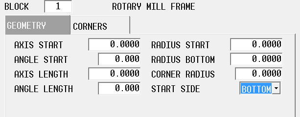
Rotary Frame - Universal
A rotary mill frame is similar to a mill frame, except the rotary frame is wrapped around a cylinder. Rotary Frame block supports the creation of frames with or without uniform corners.
The Universal Rotary Frame block contains fields on two tabs: Geometry and Corners. The geometry parameters are entered on the Geometry tab:
Refer to the Field Glossary for definitions of the Universal Rotary Frame block fields:
Each corner of a frame can be programmed with a radius or chamfer of a different size, on the Corners tab:
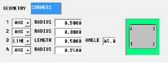
Select Line or Arc for each corner:
-
Specify radius for arcs.
-
Specify length and angle for lines.
|
|
If the corner should have neither, the geometry should be left as an arc with radius of 0.00, which is the default. |
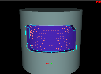
Here is an example of a Rotary Frame:
Rotary True Type Font - Universal
Rotary Stick Lettering - Universal
Rotary True Type Font - Universal
Rotary True Type Font is available with Universal Rotary configuration only.
Refer to the Field Glossary for definitions of the Universal Rotary True-Type Lettering fields:
|
|
||
|
|
||
|
|
|
Available Fonts for Mill True-Type Lettering |
|
|---|---|
|
Arial (default) Arial Black Comic Sans MS Courier New Franklin Gothic Medium Georgia Impact Lucida Console Lucida Sans Unicode Marlett |
Microsoft Sans Serif Palatino Linotype Sylfaen Tahoma Times New Roman Trebuchet MS Verdana Webdings Wingdings |
Rotary Slot - Universal
The Rotary Slot block creates a line or arc shape of any width on a cylinder.
|
|
See Mill Slot of the Conversational Milling chapter for additional information. |
Refer to the Field Glossary for definitions of the Universal Rotary Slot fields:
|
|
|||
|
|
|||
|
|
|||
|
|
Rotary Polygon - Universal
The Rotary Polygon data block mills a multi-sided contour with equal-length sides on a cylinder.
See Mill Polygon in Conversational Programming for more information.
|
|
See Mill Polygon in the Conversational Milling chapter for additional information. |
Refer to the Field Glossary for definitions of the Universal Rotary Polygon fields:
|
|
||
|
|
||
|
|
||
|
|
||
|
|
Rotary Stick Lettering - Universal
The Rotary Stick Lettering block allows text to be wrapped around a cylinder.
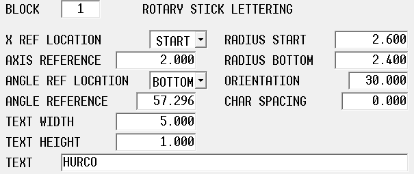
Refer to the Field Glossary for definitions of the Universal Rotary Stick Lettering fields:
|
|
||
|
|
||
|
|
||
|
|
Rotary Patterns - Universal
Rotary patterns allow you to repeat a rotary mill feature (e.g., rotary circle, rotary frame, holes) on the part. The Rotary Patterns data block is available with multiple rotary configurations; see Rotary Patterns for an explanation of the softkeys on this screen. The specific pattern data blocks for Universal Rotary are explained below.
|
|
Rotary Patterns only apply to cylindrical wrapping and therefore only apply to rotary blocks within the pattern. Use non-rotary patterns to repeat a feature on a plane Use Transform Plane when you want to repeat a non-rotary feature (e.g., mill contour, holes) on multiple sides of a part. See Universal Transform Plane. Alternatively, use Rotary Position Loop or Rotary Position Locations to index the rotary axis and repeat a non-rotary feature. |
Rotary Loop
A rotary loop defines the number and locations a feature is repeated on a cylinder. The initial mill feature is located at part zero and all subsequent copies are at a specific distance of the linear axis along the cylinder and the rotary axis arounder the cylinder.
|
|
A rotary Pattern End data block is required to end the sequence repeated in the Rotary Pattern Loop data block. |
Refer to the Field Glossary for definitions of the Universal Rotary Patterns loop fields:
|
|
Rotary pattern and standard pattern data blocks can be nested (i.e., entirely contained within another pattern). The order of execution for nested rotary pattern and standard pattern data blocks is from the inside to the outside. In the following example of nested data blocks, this is the order of execution:
Rotary Pattern Loop Only one Rotary Position data block is required for nested Rotary Pattern Loop data blocks. |
Rotary Locations
The Rotary Pattern Locations data block is used to create a list of locations of a mill feature repeated on a cylinder. Up to 999 copies can be located anywhere on the part.
Each set of locations listed on the Rotary Patterns Location data block is a specific location on the cylinder, relative to part zero. If you want the mill feature to be cut at part zero, you must define the coordinates of part zero in one of the sets of locations.
Refer to the Field Glossary for definitions of the Universal Rotary Pattern Locations fields:
|
|
A rotary Pattern End data block is required to end the sequence in the Rotary Pattern Locations data block. |
|
|
After the rotary Pattern End data block has executed, the orientation of the machine axes will remain at the position defined in the most recent Rotary Position data block. If the part program continues beyond the Rotary Pattern operation, another Rotary Position data block will be required if the axes must be reoriented to a different position. |
Rotary Rectangular
Rotary Rectangular Pattern Block is available only with the Universal Rotary configuration.
Refer to the Field Glossary for definitions of the Universal Rotary Pattern Rectangular fields:
Rotary Mirror
Rotary Mirror Pattern Block is available only with the Universal Rotary configuration.
Refer to the Field Glossary for definitions of the Universal Rotary Pattern Mirror fields:
Rotary Position Loop
The Rotary Position Loop data block defines the number and locations a feature is repeated on multiple sides of a part that can be indexed by a rotary axis, as does the Rotary Pattern Loop block described above. It is different from the Rotary Pattern Loop block in that it performs indexing and applies the pattern to non-rotary mill blocks within the loop block, as shown below.
ROTARY POSITION LOOP
MILL CIRCLE
PATTERN END
|
|
Rotary Position Loop is available only with the Universal Rotary configuration. |
Refer to the Field Names Glossary for definitions of the Universal Rotary Position Loop fields:
Rotary Position Locations
The Rotary Position Locations data block is used to create a list of locations of a mill feature repeated on multiple sides of a part that can be indexed by a rotary axis, as is the Rotary Pattern Locations block described above. it is different from the Rotary Pattern Locations block in that it performs indexing and applies the pattern to non-rotary mill blocks within the loop block, as shown below.
ROTARY POSITION LOCATIONS
MILL CIRCLE
PATTERN END
|
|
Rotary Position Locations is available only with the Universal Rotary configuration. |
Refer to the Field Names Glossary for definitions of the Universal Rotary Position Locations fields:
Rotary Parameters - Universal
The Rotary Orientation field defines the axis configuration: Rotary A/AB, Rotary B, Rotary AC, Rotary BC, and User Defined. User Defined orientation requires the Axis of Rotation (Cylinder Axis vector) and Zero Angle vector. The Zero Angle vector describes the zero-degree Cylindrical Point vector direction with respect to the current coordinate system. These vectors must be perpendicular otherwise the control will throw an error. Other Rotary Orientation selections (Rotary A/AB, Rotary B, Rotary AC, Rotary BC) are available to automatically configure the Axis of Rotation and Zero Angle vectors to describe rotary features for Hurco's current program type configurations.
Set Cylinder Radius Data to use the Radius Start value from the Rotary block or to a User Defined value. A user defined value may be used when you want to move the feature so the cylinder wrapping is referenced somewhere between radius start and bottom instead of radius start. Radius is used to calculate passes for cutter comp and for pocketing operations. It does not affect linear size of rotary font blocks, which are special cases.
Off Centerline Distance allows a +/- value for distance from centerline.
Tool Vector Angle to Cylinder Axis is the angle between the tool vector and the cylinder axis when milling. The default is 90 degrees, which means the tool is oriented to come straight in towards cylinder center.
Cylinder Retract Type controls the retract of the tool from the part. Along Tool Vector moves the tool away from the part in a direction along the tool’s axis. Along Cylinder Normal will ignore the tool vector completely and instead moves the tool in a direction that is at a right angle to the cylinder’s axis.
Pattern End
A Pattern End data block is required to end rotary pattern operations. There are no fields in the Pattern End data block.
|
|
After the rotary Pattern End data block has executed, the orientation of the machine axes will remain at the position defined in the most recent Rotary Position data block. |
If the part program continues beyond the Rotary Pattern operation, another Rotary Position data block will be required if the axes must be reoriented to a different position.
-
A Rotary Pattern Loop data block only modifies the rotary operations contained within the pattern.
-
The subsequent Rotary Position data block defines the orientation of the machine axes after the pattern is executed, and can provide a reference point if Recovery Restart is used.
-
If the Rotary Pattern End data block is the last data block of the part program, a subsequent Rotary Position data block is not necessary.
-
For non-universal program types, if a non-rotary operation data block (e.g., holes operation) is used in a rotary loop, a Rotary Position data block is required before the non-rotary operation data block to position the axes before the operation is executed in the loop.
ROTARY LOOP
ROTARY POSITION
MILL CIRCLE
PATTERN END
- For the universal program type, the Rotary Pattern Loop and Rotary Pattern Locations blocks are meant to be used exclusively with rotary operations. The combination of Rotary Pattern Loop/Rotary Pattern Locations and Rotary Position blocks with non-rotary operations is not supported and the Rotary Position Loop and Rotary Position Locations blocks should be used instead.