Universal Transform Plane
Hurco’s Universal Transform Plane feature can be used with 4-axis or 5-axis machining centers to machine non-rotary (i.e., 3-axis) milling or drilling features on multiple sides (planes) of a part. The method of orientation (angles or vectors) is established and the machine automatically moves so that the tool is positioned perpendicular to the transformed plane.
Universal Transform Plane has the following benefits:
-
Reduces setup time and potential positioning errors because the part doesn’t have to be refixtured each time the plane is transformed.
-
Allows a non-rotary milling or drilling feature to be machined on one or more sides of an irregularly-shaped work piece.
More Information Online
For more information about using Hurco's Transform Plane block, visit the Transform Plane demonstration video on YouTube.com.
Transform Plane Block
A Transform Plane block is used in a Conversational program to repeat a non-rotary feature (for example, mill contour or holes) on multiple sides of a part.
|
|
Rotary Pattern Loop and Rotary Pattern Locations data blocks can not be used within a Transform Plane operation. Non-rotary patterns cannot be in effect (i.e., must be closed with a Pattern End data block) prior to a Transform Plane operation. However, non-rotary patterns can be used within a Transform Plane operation. |
Refer to the Field Glossary for definitions of the Universal Transform Plane fields:
Follow these steps to use Universal Transform Plane:
-
Insert a Transform Plane block before the non-rotary milling or drilling block you want to transform.
-
Select the Orient Method.
-
Enter the origin point coordinates and the angles or vectors.
-
-
Create the non-rotary milling or drilling block(s) on the X-Y plane (i.e., create the milling or drilling feature as a 3-axis part). Multiple milling or drilling operations may occur within a Transform Plane operation.
-
Insert a Transform Plane End block. The Transform Plane operation ends and part zero is the reference point.
|
|
Repeat steps 1-3 for each transform (repeat of the milling/drilling feature on another side/plane of the part). |
Also see Universal Transform Plane Example.
Transform Plane End Block
The Transform Plane End block ends the Transform Plane operation and part zero is the reference point.
|
|
Stacking or nesting of multiple transform planes is allowed. In this case the Transform Plane End block is not used between transform plane moves, so the tool does not move back to part zero between transform planes. At the end of the stack, there must be a Transform Plane End block for each transform plane contained inside the stack. |
Universal Transform Plane Example
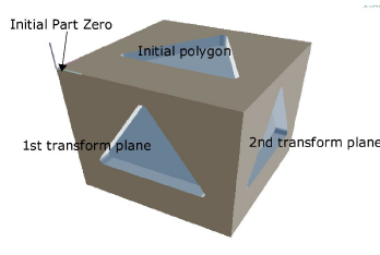
The figure below shows a non-rotary mill polygon created on the top of the part and transformed onto two additional sides.
|
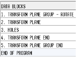
DB |
Data Block/Fields |
Value |
Notes |
|---|---|---|---|
|
1 |
Mill Polygon |
|
Creates the non-rotary polygon on the XY plane. |
|
2 |
Transform Plane |
|
Re-orients the work plane. |
|
Orient Method |
Angles |
|
|
|
Origin Point |
X0, Y0, Z-6 |
|
|
|
Rotation Angles |
R(X)90, R(Y)0, R(Z)0 |
|
|
|
3 |
Mill Polygon |
|
Creates the non-rotary polygon on the first transform plane. |
|
4 |
Transform Plane End |
|
Ends the transform plane. |
|
5 |
Transform Plane |
|
Re-orients the work plane. |
|
Orient Method |
Angles |
|
|
|
Origin Point |
X6, Y0, Z-6 |
|
|
|
Rotation Angles |
R(X)90, R(Y)0, R(Z)90 |
|
|
|
6 |
Mill Polygon |
|
Creates the non-rotary polygon on the 2nd transform plane. |
|
7 |
Transform Plane End |
|
Ends the transform plane. |
Transform Plane Groups
Transform Plane Groups allow you to easily pattern or sequence a Transform Plane feature without the need to program a series of transform planes at each location and with different angles.
Three types of Transform Plane group blocks correspond with the three methods of sequencing transform plane geometry: linear, rotate, and locations:
-
Transform Plane Group Linear—repeats a transform plane along a linear pathway with XYZ locations specified.
-
Transform Plane Group Rotate—repeats a transform plane around an axis with the angle and distance specified.
-
Transform Plane Group Locations—repeats a transform plane at specified locations using Angles or Vectors method.
Follow these steps to use Universal Transform Plane Groups:
-
Insert a Transform Plane Group block and program the fields to specify the sequence moves.
-
Insert a Transform Plane block and program to specify the transform plane moves.
-
Create the non-rotary milling or drilling block(s) on the X-Y plane (i.e., create the milling or drilling feature as a 3-axis part).
-
Insert a Transform Plane End block to end the transform plane moves.
-
Insert a Transform Plane Group End block to end the sequence.
See Universal Transform Plane Groups Example.
Transform Plane Group Linear
Repeat transform planes along a linear pathway. Refer to the Field Glossary for definitions of the Transform Plane Group—Linear block fields:
Transform Plane Group Rotate
Repeat transform planes around an axis. Refer to the Field Glossary for definitions of the Transform Plane Group—Rotate block fields:
Transform Plane Group Locations
Repeat transform planes at specified locations using angles or vectors. Refer to the Field Glossary for definitions of the Transform Plane Group—Locations block fields:
Transform Plane Group End
Ends the Transform Plane Group sequence.
Keep in mind that when using Transform Plane Groups the group block and group end block must bookend the transform plane and non-rotary feature blocks, as shown in the example below:
Universal Transform Plane Groups Example
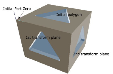
The figure below shows a non-rotary mill polygon created on the top of the part and transformed onto two additional sides, using a Groups method. Note that the geometry is the same as the Transform Plane example provided above, but the Transform Plane Group Locations block specifies the transform planes. In this case the polygon data block is created only once, simplifying program maintenance if it needs to be changed.
|
DB |
Data Block/Fields |
Value |
Notes |
|---|---|---|---|
|
1 |
Transform Plane Group Locations Orient Method = Angles
|
3 Locations: X0, Y0, Z0, X0, Y0, Z-6, X6, Y0, Z-6, |
Specifies the locations of the initial polygon and the 1st and 2nd transform planes. |
|
2 |
Mill Polygon |
|
Creates the non-rotary mill polygon on the XY plane. |
|
3 |
Transform Plane Group End |
|
Ends the transform plane. |