A
—the A end position of the move (fields are inactive for a non-rotary machine).
—in a Rotary Position block, the rotary-axis coordinate (angle) where the mill feature will be located on the part.
—the rotary-axis coordinate (angle) relative to Part Zero A.
—the rotary-axis coordinate (angle) of the center point.
—the offset from true part zero. Field is available when Disable Centerlines is No in Part Setup. Program the value in order to draw the program properly on the Graphics screen.
—the rotary-axis coordinate (angle) of the reference corner of the frame.
—the distance (angle) on the rotary-axis between each repetition of the mill feature.
—the rotary-axis coordinate (angle) for the ending point of the line.
—the rotary-axis coordinate (angle) from the reference corner.
-
A Length is positive if the location of the frame is clockwise from the reference corner.
-
A Length is negative if the location of the frame is counter clockwise from the reference corner.
—the offset for the A axis, to be added to the A dimension in the data block.
—the rotary-axis start point coordinate, calculated with data from the previous segment. The value of A Start can be changed only in the segment in which it was created.
Adaptipath Link Length Tolerance Multiplier
—used by Adaptipath to control whether tool retracts and plunges when linking path. This parameter is a multiplier of tool diameter. Default is 5.0. For example, at 5.0, if the distance from the end of one pass to the start of the next is greater than 5 times the tool diameter the tool will retract and rapid over.
—indicates Pressure OK or Pressure Low. Pressure OK is required to begin an ATC operation.
Allow Bore & Ream Cycle Interrupt
—controls whether the Interrupt console button will interrupt a bore or ream cycle. Default is No. When No, the cycle will complete before retracting tool. When Yes, the cycle will stop and the tool will retract when the Interrupt button is pressed.
—if Yes, UltiPocket will plunge outside the pocket, moving through the open side of the pocket boundary. May be used with open contours only; cannot be applied to frames, circles, or ellipses because they cannot be programmed with open contours.
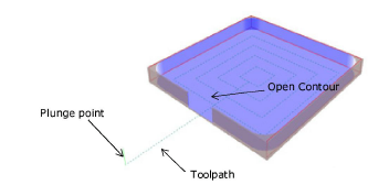
The Operator Specify Pocket Start parameter must also be set to Yes.
The contour Pocket Type must be set to Inward.
|
|
The plunge point should be placed near the open side of the contour outside the pocket. The tool moves through this opening near the approximate center. The software verifies the tool will fit through the opening and generates an error message if it will not. |
—allows variable values to be left blank when Yes.
Alt Dwell Lt Side
—controls washdown coolant flow on the left side of the machine enclosure on certain machines. Used in conjunction with other washdown coolant parameters. See Machine Parameters – General 1 in Getting Started with WinMax Mill for more information.
Alt Washdown Dwell
—controls washdown coolant flow on the right side of the machine enclosure on certain machines. Used in conjunction with other washdown coolant parameters. See Machine Parameters – General 1 in Getting Started with WinMax Mill for more information.
Alt Washdown Off Time
—the time the washdown coolant flow cycle is paused, on certain machines. See Machine Parameters – General 1 in Getting Started with WinMax Mill for more information.
—in Pattern Loop Linear, the angle (in degrees) between the defined line and the X positive axis. A positive value is counterclockwise (CCW) from the 3 o'clock position, and a negative value is clockwise (CW) from the 3 o'clock position.
—in Pattern Mirror Image, the orientation in degrees of the mirror line (which passes through the X-Y dimensions); measured from the 3 o'clock position. A positive value is CCW.
—in Rotary Pattern Locations, the angle coordinate where the mill feature will be located on the part.
—in Rotary Patterns Mirror, the orientation of the mirror line which passes through the point defined above (measured in XY from 3 o’clock).
—rotary-axis coordinate (angle) of the center point.
—the distance (angle) on the rotary-axis between each repetition of the mill feature.
—in Rotary Rectangular, the distance between the patterns along the rotary axis.
—axis coordinate for the ending point of the line or arc.
—rotary-axis coordinate (angle) from the reference corner.
-
Angle Length is positive if the location of the frame is clockwise from the reference corner.
-
Angle Length is negative if the location of the frame is counter clockwise from the reference corner.
—the number of times the programmed routine will be repeated along the rotary axis.
—the reference coordinate of the point where text begins/ends, relative to the Angle Ref Location.
—the location of the reference point in the text: Bottom of text, Top of text, Center of text.
—rotary-axis coordinate (angle) for the segment starting point.
The value of Angle Start can be changed only in the segment in which it was created.
—indicates if the APC table is clamped or unclamped.
—indicates if the APC door is Open and Unlocked, Closed and Unlocked, or Closed and Locked.
—indicates whether APC table is in the Up or Down position.
—applies the automatically-calculated border to the top of the stock, in Stock Geometry. The border is automatically applied to the bottom. Field is available when Manual Stock Sizing is set to NO.
Apply Same Z Start
—when creating multiple data blocks of the same type, toggling this selection on results in the user being prompted only once for the Z start (if possible). Uses the same Z start for each block.
—the feed rate to use for the initial touch of the part during a manual mode Part Setup probing cycle. No measurement is taken at this feed rate, it is simply used to locate the part feature to be probed. If running a part probe cycle in auto mode (through a conversational data block or NC Program), this feed rate begins after the Fast Start Feed rate beginning at the probe starting point.
—the radius of the arc, if known.
—the type of Argument, String or List, and variables in a NC Program Call block.
—assumes a feedrate increment of .1 when Yes is selected.
—specifies Yes or No. When Yes is selected, the Minimum Length and Leading Symbol fields appear so that a placeholder can be used to achieve consistent serial number length. Default is Yes.
—indicates At X, At Y, and At Z positions. All three are required for ATC to begin.
ATC Disable
—disables all automatic tool changer functions. See Machine Parameters – General 2 in Getting Started with WinMax Mill for more information.
—indicates Closed or Open position. Closed is required for ATC Status Home.
—indicates if the ATC is at a position where it can stop.
—indicates Z At Height and X/Y At Position (VTXU only).
—indicates if ATC is in Home position and calibrated. Home is required for ATC or APC cycle to begin. Home is defined as ATC Door closed, Exchange Arm at 0°, Tool Holder at 0°, and Magazine In Pos (1).
ATC Z-Axis Move to Zero Position
—in HMX only, moves the Z-axis to zero position at the end of a tool change. See Machine Parameters – General 2 in Getting Started with WinMax Mill for more information.
—indicates Z is at Machine Tool Change Height.
Auto Balance Enable
—adjusts the balance between the motion card and the servo drives at the start of calibration and run program. See Machine Parameters – General 2 in Getting Started with WinMax Mill for more information.
Automatically Load Unmatched Tools As Manual
—automatically loads unmatched tools from newly-loaded conversational part programs:
-
YES—new tools from the newly loaded program (that are not in the Tool & Material Library) are automatically added to Manual.
-
NO—requires new tools to be matched (see “Part Program Tool Review” section for more information about matching tools.)
Automatic Centerline Calculation
—specify Yes or No to enable automatic centerline calculation.
Automatic Safe Repositioning Vector Retract Override
—When set to OFF the tool automatically retracts, reorients, and plunges, using a series of moves computed automatically that do not violate machine limits. Set to ON to override the automatic repositioning and enter a retract distance along the tool vector from the target position. This value is absolute and starts at the Retract Clearance plane when entering Automatic Safety Repositioning.
|
|
The control will retract to either the Retract Clearance distance or to the Vector Retract clearance depending on which value is greater. |
In Conversational programs, available only with Universal program types.
See Automatic Safe Repositioning Command Buffer On (G08.1) in NC Programming for more information about Automatic Safe Repositioning.
—in the Program Parameters Probing tab, select the method of checking tools calibrated with the probe:
-
Incoming Tool—tool is checked after it is inserted into spindle
-
Outgoing Tool—tool is checked before it is removed from the spindle
-
Both—checked before and after cut
Specify tolerances in the Length Tolerance and Diameter Tolerance. For more information about tool monitoring, see Tool Quality Monitoring in Probing.
—enables WinMax to automatically select new origin-point coordinates in a transform-plane data block for each side of a part in multi-sided programming (based on the geometry selected). Transform can be used to edit origin position if desired. Leaving this toggle off enables the user to specify origin-point coordinates in a transform-plane data block. This setting is used with the 3D DXF/Solid Model Import option.
Aux Output 1-12 Confirmation Enable
—enables a confirmation signal for completion of each Auxiliary M-code Output. See Machine Parameters – Auxiliary Outputs in Getting Started with WinMax Mill for more information.
—axis coordinate where the mill feature will be located on the part.
—whether the spindle is in tool-change position or not. This is a read-only field.
—Z-axis coordinate of the center point.
—the distance between each transform plane in the sequence, along the rotation axis.
—in Rotary Patterns, the distance on the X-axis between each repetition of the mill feature. The right-hand rule determines if Distance is positive or negative.
—in Rotary Rectangular, the distance between the patterns parallel to the rotary axis.
—axis coordinate for the end point. The Axis End value is the depth of the cut at the end point and is carried forward from the previous segment. Retain the Axis End value or type in a new value.
Axis Feedrate Override Max (%)
—Parameter not accessible by the user. Contact a Hurco Certified Service representative for assistance.
Axis Feedrate Override Min (%)
—sets the Axis Feedrate Override Minimum value. See Machine Parameters – Calibration and Warm-up in Getting Started with WinMax Mill for more information.
—the axis coordinate measured from the reference corner.
-
Axis Length is positive if the reference corner is at the left side of the rectangle.
-
Axis Length is negative if the reference corner is at the right side of the rectangle.
—the status of the machine’s limit switches as each axis calibrates.
—the number of times the programmed routine will be repeated along a line parallel to the rotary axis.
—the reference coordinate of the point where text begins/ends, relative to the Axis Ref Location.
—the location of the reference point in the text: Start of text, End of text, Center of text.
—axis coordinate for the segment starting point. Field is read-only in other segments and can be changed only in the segment in which is was created.
—in Rotary Frame, the axis coordinate of any one of the four corners of the frame. This corner becomes the reference corner.