S
—the current spindle RPM percentage set on the Spindle Speed override knob.
—the current spindle speed. In some instances, “L” or “H” may be displayed next to the field to indicate low or high gear in use.
—when set to OFF the tool will retract to machine limits; set to ON to enter a tool tip clearance.
—a part-relative safety area to prevent the cutting tool from colliding with fixtures or other equipment. The Safety Work Region created in Part Setup is saved with a conversational part program; the Safety Work Region is not saved with NC programs.
—specify Yes to save only the current program; specify No to save all loaded programs; default is No.
—the number of minutes between each autosave; range is 1-255.
—when set to Yes, an NC State file is saved with the NC program, in the same directory and with the same name. Default is No.
—(desktop only) select Dual Screen or Single Screen display. Default is Single.
—see Enable, X Position, and Y Position.
—the segment number within the Mill Contour operation. The system determines the number by the position of this segment in the contour.
—the feed rate to use for setup moves near the probe. For example, when dropping down next to the probe to measure diameter, the drop down move uses this feed rate. This value is also used for calibrating the probe and the initial touch when determining deflection offsets.
—in Tool Setup, appears when the tool type is Back Spotface and represents the diameter of the tool shank.
—the shape of the slot, either line or arc.
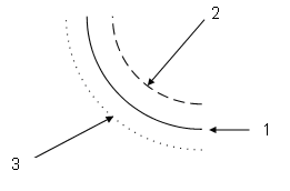
—the angle formed by points 1 and 3 defining the shape with a range from 20° to 160°.
Shift
—see Part Zero Z Shift.
—view all file extensions when opening files; default is No (only displays HWM, HD3, HD5, FNC, HNC, and NC file types).
—the type of graphic display: Show All, Tool Path, or Solids.
Show Roughing Tool Path for 2D Surfaces
—turn on to show all the roughing tool path, applies only to Toolpath graphics.
Show Roughing Tool Path for 3D Surfaces
—turn on to show all the roughing tool path for 3D Molds and Swept Surfaces, applies only to Toolpath graphics.
— toggle on/off to show or hide the solid edges of the graphic. This setting is used with the 3D DXF/Solid Model Import option.
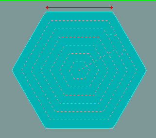
—specifies the length of the side. This field is available when the Side Length Sizing Method is selected.
—the spare tool for tool quality monitoring. See Tool Quality Monitoring in Tool Probing.
—specifies the diameter of the circle. This field is available when the Outer or Inner Diameter Sizing Method is selected.
—how the polygon size is established:
-
Outer Diameter—the diameter of a circle that encompasses the outside of the polygon, touching it at the corners:
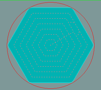
-
Inner Diameter—the diameter of a circle contained within the polygon, touching at the center of each edge:

-
Side Length—the length of one side of the polygon:
—the X or Y axis as the skew axis. There is no skewing in Z.
—the geometric feature for the Part Skew cycle.
—the location where the probing process begins. The easiest method for entering the start positions is to jog the probe down to the desired start location and press the Store Position key. A single push of this key automatically enters all three coordinates (X, Y, and Z) for one Start position.
—in Bolt Circle, Enter up to 24 positions that should be skipped (not drilled).
—the feed rate used when taking measurements after the initial deflection. The default value is 4 mm per minute for a touch probe, 25.4 mm per minute for a laser probe.
—the maximum allowable deviation from the tool path. The range is 0.0000 to 0.0500 inches (0.0000 to 1.2700 mm); default is 0.0005 inches (0.01270 mm). This corresponds to NC code G05.2
—Distance between gridlines on the graphic grid when using the Snap to Grid option. This setting is used with the 3D DXF/Solid Model Import option.
—positions the softkey menu to the right or left of the screen; default is Right.
—Save and load a solid graphic simulation (.sim file). When a solid part has been drawn, select the Save button to save the .sim file. Select the Load button to load and open a .sim file.
—the spindle speed for the tool. Entering a value in the Speed field in a data block overrides the Tool Setup value, for that data block.
See Feed and Speed Calculations in Getting Started with WinMax Mill for more information.
The range is set in Machine Specifications in Utilities.
—whether the spindle is oriented or not, indicating if it is in a safe position for a tool change. Use the Orient softkey to orient the unoriented spindle.
—indicates No Alarm or Alarm. No Alarm is required to begin an ATC operation.
—indicates “ON” when spindle unclamp button is depressed, “OFF” when it is not.
—used only when measuring tool diameter. Specifies an additional distance to leave between the tool and tool probe when determining the tool diameter. This value can be adjusted to optimize probe cycle time.
—the percentage of used power at the current RPM.
—the percentage of full load on each axis as the program runs. The load is displayed in a bar graph format, with colors progressing from green to yellow to red to indicate the percentage of load from 0 to 150%.
—indicates if the spindle shuts off at 0 RMP at the end of each cycle while moving to the next hole location. Default is Yes.
—the spindle speed when the Spindle Usage field is set to either CW or CCW. When the operator sets the diameter setting for the tool probe, the Spindle RPM field will be set to a suggested value – this value may be overwritten by the operator. The suggested value for RPM is only done when the tool is first entered.
—indicates if the Spindle is Oriented or Not Oriented, and clamped or unclamped. Oriented is required for ATC to begin.
—the point at which the spindle stops rotating after drilling the hole in a Gun Drill cycle. This field may be set to be the Z Bottom or the Z Start position.
In Bore Rapid and Ream Rapid data blocks, indicates if the spindle stops at the bottom of the hole (Z Bottom) and during retract. Options include:
-
Z Bottom— stop spindle at the bottom of the hole and during retract.
-
Continue — spindle remains active at the bottom of the hole and during retract.
—specifies the direction the spindle should turn during the probe cycle. Choices are: manual (free rotating), oriented, clockwise (CW) or counter clockwise (CCW).
|
|
The default value for a touch tool probe is the reverse of the programmed tool. For example, if the tool is CW, Spindle Usage for a touch tool probe will default to CCW. For a laser tool probe, Spindle Usage value defaults to the programmed tool direction. |
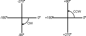
—in 3D Mold, the starting value of the angle of revolution for XY Revolved About X and XZ Revolved about Z. When determining Start Angle, remember that 0º is where the contour begins and is located at the 3 o'clock position. For more information, see 3D Mold in Conversational Programming.
-
The difference between the start and end angle determines the degrees that the 2D profile revolves about the axis.
-
Start and End angles can be entered as positive or negative numbers. CCW motion is programmed as a positive number; CW motion is programmed as a negative number:
—in Bolt Circle, the angle of the circle measured counter-clockwise from the 3 o'clock position to the first hole. This angle may be specified to the nearest one-thousandth of a degree.
—in Mill Thread, the starting angle for the threading operation in the XY plane. Zero Angle is at the 3 o’clock position.
—in Part Probing, the three probe deflection points (Start Angles 1, 2, 3). Relative to the 3 o’clock position, and increasing counter-clockwise as viewed from above the part, the default angles are 0, 120, and 240, respectively. Change the angles if the part contains geometry that interferes with the defaults.
—in Pattern Loop Angular and Rotate, the angle value between the original pattern and the location of the first pattern created by this routine. If this location is the same as the original programmed pattern, the value in this field will be zero.
—in Mill Circle and Rotary Circle, the location of the plunge start point on the circle, -360 to +360. A positive value is counterclockwise (CCW) from the 3 o'clock position, and a negative value is clockwise (CW) from the 3 o'clock position. Default is 0. Field is not available when Milling Type is Pocket Boundary with Pocket Type Outward or when pocket with user defined pocket start points is used.
—specifies if the threading operation should start at the center of the threads. Default is Yes. If set to No, the Blend Offset value from Program Parameters is used. This field is available only when the Internal Thread field is set to Yes.
—the number of the first block in the program to be changed or run.
—the shape that is used to close the slot at the specified start point:
-
Line—flat edge connects the top and bottom edges of the slot, passing through the programmed start point.
-
Append Arc—rounded edge; center of semi-circle is programmed start point.
-
Include Arc—rounded edge; outermost edge of semi-circle is programmed start point.
—indicates if the start coordinates for a Probe Part Setup are relative to the machine zero or to the active part zero.
—the number of the first job to be run.
—indicates Off or On. On is displayed when the Start Cycle button is pressed.
—tool plunges on or around the middle of the side selected: Bottom, Right, Top, Left. Default is Bottom. Plunge will be referenced from the middle of the chosen wall, or at the end of a corner if the corner is larger than half of the wall length.
This field is not available when Milling Type is Pocket Boundary with Pocket Type Outward, ADP Zigzag, or ADP 1-way, or when pocket with user-defined pocket start points is used.
—in HD3 Serial Number Lettering, the characters for the first serial number. The sequence can contain any combination of alpha or numeric characters, but the last character in the sequence must be a digit (number). This field appears only when User-provided Data Origin is selected. Default is 1.
—the type of segment (arc or line) to connect passes of normal cut direction.
— the percentage of tool diameter engaged in each cutting pass in a pocket milling operation.
—the distance between cutter passes. Ultimately, this dimension determines the surface finish of the part. A larger step size machines faster but leaves a rougher surface. A smaller step size machines more slowly but leaves a smoother surface. Step size significantly affects the drawing speed of the graphics screen.
—indicates the full file path location, including the file name, for the desired STL file for use in Stock Geometry. This field is displayed when USE PROGRAM NAME is set to NO when STL FILE is selected as the STOCK TYPE in the Stock Geometry screen.
 Step Size |
|
|
|
|
|
|
|
|
|
|
|
|
|
|
|
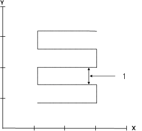
—leaves or removes extra material on the surface of a 3D contour. Can be used for roughing, undersizing, or oversizing a surface. A Ball-Nosed End Mill must be used to maintain a uniform stock allowance dimension over the complete 3D contour. A positive stock allowance value programmed using a Flat End Mill leaves sufficient material for a finishing pass:
|
|
|
|
|
|
1 Print Dimension |
|
|
2 + Stock Allowance |
|
|
3 - Stock Allowance |
|
|
|
—specifies whether the Finish XY and Finish Z parameters used are those set in Program Parameters (Program Parameters mode) or those set in the individual data blocks (Data Block mode).
|
|
In Data Block mode, the Allowance tab is active in the data block, and the values entered there supersede the Finish XY and Finish Z values from Program Parameters. Finish XY and Finish Z must be entered in the data block; they are not applied automatically. To use the Finish XY and Finish Z values entered in Program Parameters while Data Block mode is enabled, select the Copy Allowances from Parameters soft key when entering Finish XY and Finish Z values in the Allowance tab of the individual data block. This method can increase data block programming speed and consistency while decreasing entry errors. When Milling Type is ON, only the Finish Z parameter appears in the Allowance tab. |
—turn on to show the stock outline, which is set in the stock geometry screen (appears as green solid line). Refer to Stock Geometry in Part Setup for more information.
—shows the stock in a solid (Opaque) or clear (Translucent) view, in graphics display. Default is Opaque.
—the type of stock in Stock Geometry screen:
-
Box—enables settings for X length, Y length, Z length of stock box or cube.
-
Cylinder—enables direction, length, and radius of cylinder.
-
STL File—enables import of a solid model (STL file) that is used to represent the stock.
|
|
The STL file must be exported from the CAM system in metric units. Use in either metric or inch after import into WinMax. |
—pauses program operation until further input from the operator:
-
If set to Yes, the program is stopped, the spindle goes to its Z Top position, and the coolant shuts off.
-
If set to Optional, the behavior is dependent on the state of the Optional Stop setting on the Auto screen. (Refer to Auto Mode Monitoring for information about the Optional Stop On/Off softkey.) If the Optional Stop is enabled on the Auto screen, the program will be stopped (same as Yes). If it is not enabled, no stop occurs (same as No).
-
If set to No, no stop occurs.
|
|
Press the flashing Start Cycle button to continue with the part program. |
—in Universal Rotary Position block, Yes pauses program execution after the Rotary Position data block is executed. To restart the program, press the Start Cycle console button.
—stop bits signal the end of the transmission of data. Choose the size for the Stop Bit.
—the destination for the probed length and/or diameter value.
—whether to store the probed skew angle from the probe part setup block in X/Y Skew or Part Zero C. When X/Y Skew is selected, the angle provided in Part Setup is used as the new zero angle. For Part Zero C, the c-axis angle is physically corrected by the degrees provided in Part Setup. For machines without a C axis, this selection defaults to X/Y Skew and cannot be changed.
—the stylus tip diameter, available on the specification sheet for the probing equipment.
—the length of the probe stylus.
—the width of the probe’s stylus along the Probing Axis (touch tool probe only).
Surface Finish Quality (Roughing Default)
—the SFQ value for the roughing operation.
Surface Finish Quality (Finishing Default)
—the SFQ value for the finishing operation.
—the side of the Along contour on which the profile is cut:
-
When set to Right, the profile is cut to the right of the contour forming a surface to the right of the along contour.
-
When set to Left, the PROFILE is cut to left of the contour creating a surface to the left of the along contour.
—the tool surface speed in feet per minute (or meters per minute), See Feed and Speed Calculations in Getting Started with WinMax Mill for more information.
—in User Interface Settings, select Yes or No to switch, or swap, the left and right screens on dual-screen consoles or use the console keys ctrl + INPUT or F + INPUT on Max5 consoles to swap screens. Use the same key combinations to switch back.
—the angular distance from the start point to the end point around the center point. The range is -360° to 360°.