C
—the C end position of the move (fields are inactive for a non-rotary machine).
—in Rotary Position Block, the rotary-axis coordinate (angle) where the mill feature will be located on the part.
—in Rotary Position block, the rotary-axis coordinate (angle) relative to Part Zero C.
—in Rotary AC Contour block, the rotary-axis coordinate (angle) for the first segment’s starting point.
—the rotary-axis coordinate (angle) of the center point.
—the offset from true part zero. Field is available when Disable Centerlines is No in Part Setup. Program the value in order to draw the program properly on the Graphics screen.
—the rotary-axis coordinate (angle) of the reference corner of the frame.
—the distance (angle) on the tilt axis between each repetition of the mill feature.
—the rotary-axis coordinate (angle) of the line or arc end point.
—the rotary-axis coordinate (angle) from the reference corner.
-
C Length is positive if the location of the frame is clockwise from the reference corner.
-
C Length is negative if the location of the frame is counter clockwise from the reference corner.
—the offset for the C axis, to be added to the C dimension in the data block.
—the C-axis coordinate start point calculated with data programmed in the Start segment. The value of C Start can be changed only in the segment in which it was created.
CAL to LS Velocity A, B, C
—sets the feedrate for the A, B, or C axis as it moves toward the calibration limit switch during a machine calibration cycle. See Machine Parameters – General 2 in Getting Started with WinMax Mill for more information.
CAL to LS Velocity X, Y, Z
—sets the feedrate for the X, Y, or Z axis as it moves toward the calibration limit switch during a machine calibration cycle. See Machine Parameters – General 2 in Getting Started with WinMax Mill for more information.
—the diameter (D) of the Laser Calibration Tool (laser tool probe only). This value can be obtained by measuring the diameter of a precision dowel or a laser calibration tool.
—the height (H) of the Laser Calibration Tool (laser tool probe only). This value can be obtained by measuring the height of a precision dowel or a laser calibration tool.
—the length (L) of the Laser Calibration Tool (laser tool probe only). This value can be obtained by measuring the length of a precision dowel or a laser calibration tool.
—the center location of the beam in X (laser tool probe only). Do not change this value after the Laser Tool Calibration cycle has been run, unless you re-run the cycle. The user enters an approximate value then the laser calibration cycle determines the precise location.
—the center location of the beam in Y (laser tool probe only). Do not change this value after the Laser Tool Calibration cycle has been run, unless you re-run the cycle. The user enters an approximate value then the laser calibration cycle determines the precise location.
—the coordinate point of the center of the part on the X axis.
—the coordinate point of the center of the part on the Y axis.
—the coordinate point of the center of the part on the Z axis.
—the Center X machine coordinate location. This field appears upon completion of the probing cycle.
—the Center Y machine coordinate location. This field appears upon completion of the probing cycle.
—the tool corner angle.
Chamfer Distance/Fillet Radius
—once the operator has designated a chamfer or fillet action, this value indicates the chamfer length or fillet radius that will be used to insert the corner element between selected entities. This setting is used with the 3D DXF/Solid Model Import option.
—specifies if the Finish SFQ should be changed for the block range.
—specifies if the Rough SFQ should be changed for the block range.
—the tool used in the block s to which changes will be made. Blocks using this tool will be changed. (This field appears only for the Change Feeds and Speeds by Tools screen.) See Change Tool Number in Getting Started with WinMax Mill for more information.
—the new Z-Start position.
—the height of the text.
—the maximum number of bits sent back and forth at one time.
—the character width. The width includes the character left-justified, plus some spacing between it and the next character to be milled. Spacing between the characters is equal to the tool's diameter.
|
|
Because cutter compensation is not used in this routine and letter contouring follows the center of the tool, character spacing can be adjusted by adjusting the tool diameter in Tool Setup. |
—the amount of additional space to add between each character. Leaving at zero will use the default character spacing for the selected font.
Check Calc Assist Inconsistencies
—this setting is useful when there are slight discrepancies or conflicts in contour data; for example, as happens occasionally with contours imported using DXF, due to bad segment connections in the DXF file. When set to Yes, an error message is generated when these inconsistencies are present in a contour segment. When set to No, the contour is allowed to draw and run, as long as there is enough relevant data to generate valid geometry.
—the feed per flute.
Chip Removal
—the status of the chip auger.
Chip Removal Off Delay Time
—sets the time the chip conveyor/auger cycles off, when Chip Removal On/Off Delay is enabled. See Machine Parameters – Coolant in Getting Started with WinMax Mill for more information.
Chip Removal On Delay Time
—sets the time the chip conveyor/auger cycles on, when Chip Removal On/Off Delay is enabled. See Machine Parameters – Coolant in Getting Started with WinMax Mill for more information.
Chip Removal On/Off Delay Enable
—enables the Chip Removal Delay. See Machine Parameters – Coolant in Getting Started with WinMax Mill for more information.
—the maximum distance the cutter deviates from the true arc path.
—the number of times to automatically repeat the probe cycle of a circular feature. After each pass the probe positions to the new center location and runs the cycle again. Multiple passes will provide better data because each pass starts closer to the true center. A poor starting location yields inaccuracies due to the diameter of the stylus and not being on line with the center. The default value is 2.
|
|
This information is specific to each installation and is stored on the hard drive. If the hard drive is replaced or formatted, the above information must be restored. Refer to the Getting Started with WinMax Mill manual for information about restoring parameters. |

|
|
When the part probe is used, it must be activated by the control. For this to occur, the control needs to know when the probe is in the spindle. WinMax provides a Probe tool type in the Tool Setup screen. Before using the part probe, enter the part probe as a tool in Tool Setup:
The control activates the probe hardware when the number in the Tool In Spindle field matches the probe’s Tool number. |

Clear Selection on Action Change
—automatically clears all selected elements when switching from one type of action to another, such as from selecting elements to editing elements.
—the feed at which the tool enters the hole at the top and bottom to be certain that the tool is closed.
—the color of the path left by the tool in Solid Graphics, set in Advance Tool Settings screen. The default selection is Sequential, where tools are represented in the following order by color:
-
Yellow—1st tool
-
Orange—2nd tool
-
Violet—3rd tool
-
Green—4th tool
-
Gray—5th tool
-
Blue—6th tool
-
Cyan—7th tool
-
Magenta—8th tool
-
Tan—9th tool
-
Lime—10th tool
Alternatively, a specific color can be assigned to a specific tool by changing the selection in the field.
—the current color scheme for the NC Editor screen, including sub-menus. Select the current color scheme to access options to change the color scheme. Options include, Light, Dark, and Dark (High Contrast). Background and foreground colors for specific syntax types are automatically based on the selected color scheme.
—whether the screen displays in the light mode, dark mode or default system theme. Requires WinMax restart in order for a change to take effect. When set to Default, a prompt displays during the WinMax system boot enabling the selection of a different system theme.
Selecting Yes in the WinMax boot prompt indicates a desire to switch to dark mode following a WinMax restart. Selecting No maintains the light mode system theme. If Ask Again Later is selected, the same prompt is presented again the next time WinMax boots up.
—the current NC comment color. The color can be changed by selecting the Change... button or the Change Comments Color softkey.
—in Machine Function data block, when M70 is selected, indicate Yes or No to require the APC READY button to be pressed before continuing operation after a pallet change.
—determines the distance from the tool tip to the desired point on the tool where contact is made with the part, moving the contact point up the tool. This offset modifies the effective tool length anytime Tool Setup is used in conversational programming to set up a tool. This offset also applies to NC programs when the Length Offset table is not used to set the tool length.
This field is only available in Tool Setup when Chamfer Mill is selected for the Tool Type.
—the X location (in machine coordinates) of the tool probe (touch tool probe only). When the machine is at this location, a tool will touch the center of the tool probe stylus. To enter these values easily, insert a tool in the spindle and jog down to the tip of the probe. When the tool tip is centered over the stylus, press the Store Position key on the jog controls.
—the Y location (in machine coordinates) of the tool probe (touch tool probe only). When the machine is at this location, a tool will touch the center of the tool probe stylus. To enter these values easily, insert a tool in the spindle and jog down to the tip of the probe. When the tool tip is centered over the stylus, press the Store Position key on the jog controls.
—determines the gap allowed in a contour when creating a pocket. This setting is used with the 3D DXF/Solid Model Import option.
—when creating elements of the same type (holes, frames, etc.) these elements are considered part of the same plane if within this measurement tolerance.
Control Power Off Time
—turns the control off after the specified period of inactivity. See Machine Parameters – General 1 in Getting Started with WinMax Mill for more information.
—the coolant used for the tool. Coolant is programmable on a tool-by-tool basis. The choices are Off/None, Primary, Secondary, or Both when the cursor is at the Coolant field. Select Primary for machines equipped with a coolant system, Secondary for machines equipped with a secondary coolant system (i.e. through spindle coolant), and Both for machines with two coolant systems.
—in the DRO, the coolant status.
Coolant Delay Time
—the time the program pauses when the coolant is enabled. See Machine Parameters – General 1 in Getting Started with WinMax Mill for more information.
—indicates Level OK and Filter OK. Both are required for tool coolant operation. Available with the coolant through spindle (CTS) option.
—the coordinate system for the end position of the move, either Part or Machine.
—in Mill Slot, the blend radius for the corners of the Start Cap or End Cap, if either or both are set to Line.
—in Mill Frame and Rotary Frame, the radius of the reference corner when all four corners of the frame will have the same radius. See Mill Frame for more information.
—the X position of the intersection. This field appears when the Probing cycle is finished.
—the Y position of the intersection. This field appears when the Probing cycle is finished.
—the status of the chip auger.
—in Auto screen, the reference time used to determine when the offset is applied, in Linear Thermal Compensation. Time can be changed during program run. Time is paused when program is finished running.
—available when the Use Cusp Height field is set to Yes in Swept Surface parameters. Specifies the step size for ball and flat end mills.
—provide custom filename extensions to enable loading of NC files that use the extensions (for example, NCC, TAP, TXT). Separate multiple entries with a comma.
—the programmed tool automatically follows the finished contour of the part with cutter compensation. Without cutter compensation, the center line of the programmed tool follows the print line.
-
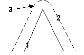
Insert Arc—Inserts a tangent arc to connect two line segments, or a line segment and an arc segment (when the two cutter compensated segments are offset and do not intersect).
|
|
|
1. Programmed Tool Path |
|
|
2. Cutter Compensated Path |
|
|
3. Completed path using the Insert Arc parameter |
|
|
|
|
|
|
-
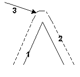
Insert Lines—Joins the cutter compensated lines and arcs as described below:
-
Two line segments are extended until they intersect (provided they form a 90º or greater angle). If the lines form an angle of less than 90º, a line is inserted to connect them.
-
Line and arc segments have the line segment extended, and a tangent line to the arc segment inserted and extended until the lines intersect (provided they form a 90º or greater angle). If the segments form an angle of less than 90º, a line is inserted to connect them.
-
Two arc segments have tangent lines (to the arcs) inserted and extended until the lines intersect (provided the extended tangent lines form a 90º or greater angle). If the extended tangent lines form an angle of less than 90º, a line or arc is inserted to connect them.
|
|
|
1. Programmed Tool Path |
|
|
2. Cutter Compensated Path |
|
|
3. Completed path using the Insert Line parameter |
|
|
|
|
|
|
—controls the tool path while a 3D contour is machined:
-
With Contour—machines the 3D contour using the tool path originally programmed.
-
Normal—tool path follows the part at right angles to the original two-dimensional profile.
-
Spiral—(Swept Surface) machines a continuous tool path resulting in a smoother surface.
—identifies the orientation of linear cutting passes along the surface of the part in the Mill Surface data block.
—in Mill Thread, the cutter length. Displayed when Cutter Type is Multi.
—the number of cutting edges on the tool.
—the number of minutes a tool has been running in the spindle (seconds are rounded up to the nearest minute). Starts at zero unless a time is pre-set (if there is already time on the tool). When Tool Life Monitoring is enabled in Tool Utilities and Settings a second field is also displayed, where the maximum cutting time for the tool can be specified. See Life Monitoring in Part and Tool Settings for more information.
—the tool probing cycle: No Probing, Length, Diameter, Length & Diameter.
—the coordinate of a point on the mirror line.
—the coordinate of a point on the mirror line.
—the radius of the cylindrical part. If the radius is a negative number, the tool will cut the rotary mill feature (e.g., rotary circle, rotary frame) from the top to bottom. Field present for all rotary configurations except Tilt B Rotary C.
|
|
If the radius of the cylindrical part is not defined in the Rotary Parameters data block and Cutter Compensation is used in rotary lines and arcs, the machine will define the part’s radius as the distance from Z Start to the rotary centerline. |
