Lines and Arcs (Mill Contour)
Mill contour data blocks use segments to create lines and arcs in a part program. A segment is any single or combined X-Y-Z axis movement at a programmed feedrate. A series of line and arc segments can be programmed in a single data block, using different segments, to form a complete contour.
The Field Name Glossary contains definitions of all WinMax fields. The fields listed below appear on the Mill Contour screens. Fields displayed on screen may vary according to machine type, configuration, parameter settings, and/or settings in other fields.
|
|
|
|
Cutter compensation, set in the Milling Type field, determines the compensation applied to the tool path. See Cutter Compensation (preliminary) for more information. |
|
|
Pecking is the use of multiple cutting passes to optimize tool operation. See Pecking for more information. |
|
|
To use pocketing with Mill Contour, the UltiPockets option must be installed. See UltiPockets for more information. |
More Information Online
For more information about using Hurco's Lines and Arcs operations, visit the Lines & Arcs videos (Intros 16, 18 & 19, 21) on hurco.com/connect.
Start Segment
The first segment in a Mill Contour block is always a Start segment, indicated by the segment zero (0). Enter the tool that will be used for the entire operation in the Start segment - all segments in the operation will use this tool. X, Y, and Z Start coordinates are also entered in the Start segment.
Line Segment
For line segments, the Auto-Calc feature automatically calculates certain unknown dimensions after you enter sufficient data.
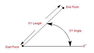
The figure below illustrates the XY Length and XY Angle in a Line segment:
-
If the X End and Y End coordinates are entered, the system calculates the XY length and the XY angle values.
-
The XY Angle is the angle of the line segment (from the start point to the end point), measured counterclockwise from the 3 o'clock position.
-
If both end points are unknown but the XY Length and XY Angle fields are programmed, the system calculates the values for the X End and Y End fields.
-
If one end point coordinate and the XY Angle field are programmed, the system calculates the values for the unknown end point and the XY Length fields.
-
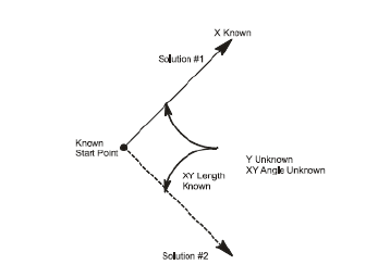
If one end point coordinate and the XY Length field are programmed, the system calculates the values for the unknown end point and the XY Angle fields. However, unless the XY Angle is known, there are two possible solutions for the unknown end point, and the correct one must be determined for the program.
-
When two possible solutions exist, the "Another end point exists" message appears and one of the two possible solutions appears in the unknown field. You can use the Draw key to view the solution in the Graphics screen. You can also use the Find Another Endpoint softkey to see the alternate solution, and view it in Graphics as well. Use the Enter key to accept either displayed solution.
The following illustration shows a line segment with unknown Y End and XY Angle:
Arc Segment
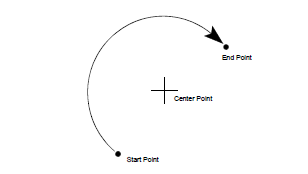
The software uses data in the Arc Segment fields as described below to perform automatic calculations:
-
The center points plus the start points or end points provide the arc radius.
-
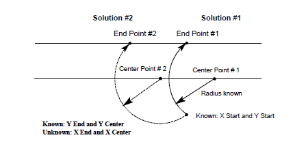
The start points and end points plus the radius provide the two possible center points.
-
Either of the end points and the center point provide the value of the other end point and the radius.
-
When a known center point, start point, or end point and radius are provided, an unknown center point is provided.
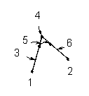
Blend Arc Segment
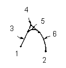
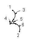
A blend arc is an arc that joins two other segments and is tangent to both. Use a blend arc to join two line segments, to join a line segment and an arc segment, or to join two arc segments. The segments to be joined must have a theoretical point of intersection.
|
|
|
|
Two Lines Joined by a |
Line and Arc Joined by a Blend Arc |
Two Arcs Joined by a |
|
1 X/Y Start |
1 X/Y Start |
1 X/Y Start |
|
2 X/Y End |
2 X/Y End |
2 X/Y End |
|
3 Segment 1 (Line) |
3 Segment 1 (Line) |
3 Segment 1 (Arc) |
|
4 Segment 1 End/ |
4 Segment 1 End/ |
4 Segment 1 End/ |
|
5 Segment 2 (Blend Arc) |
5 Segment 2 (Blend Arc) |
5 Segment 2 (Blend Arc) |
|
6 Segment 3 (Line) |
6 Segment 3 (Arc) |
6 Segment 3 (Arc) |
If the only information known about an arc is its radius, it is easier to program it as a blend arc if the segments intersect.
Reference values programmed in a previous segment to a blend arc define the start point of this segment and are displayed in parentheses. These values can only be changed in the segment in which they were created.
Some guidelines that must be followed when creating a blend arc:
-
The first or last segment of a Mill Contour data block cannot be blend arc segments.
-
Blend arc segments cannot be adjacent to one another in a program cannot be blend arc segments. For example, if segment #2 is a blend arc, neither segment #1 nor #3 can be blend arc segments.
-
Segments that are adjacent to the blend arc segment must intersect at some point in their theoretical plane. Therefore, if segment #2 is a blend arc, segments #1 and #3 must theoretically intersect at some projected point.
-
The Radius of a blend arc segment cannot be too large to be tangent to both of the adjoining segments.
-
If any coordinate (start point, center point, or end point) is important to the construction of the two segments to be blended, the segment must be programmed as an arc and not as a blend arc.
-
The Feed field is initially displayed with a value carried forward from the previous segment. This value can be accepted or changed.
|
|
A series of arcs and lines can be programmed in a single data block to form a complete contour. Press the right Arrow key to program additional Line and Arc segments for the current data block. |
Helix Segment
The software uses data in the Helix fields as described below to perform automatic calculations:
-
The Z End and Sweep Angle provide data to calculate the Lead.
-
The Sweep Angle is used to calculate the Z End.
-
The X End, Y End, and Lead values provide the Z End.
-
The Z End and Lead values provide the X End, Y End, and Sweep Angle values.
-
The X End, Y End, X Center, and Y Center values supply the Radius.
-
The Sweep Angle and either the X or Y end point provide the unknown X End or Y End.
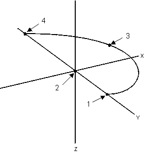
3D Arc Segment
Use 3D Arc to create a three-dimensional arc segment.
|
|
Do not confuse the 3D Arc feature with the 3D Mold Option. The 3D Arc feature is always included in the WinMax software. Refer to WinMax Mill Options for more information on the 3D Mold option. |
This diagram shows the relationships of the coordinates to each other:
|
|
|
1 Start Point |
|
|
2 Center Point |
|
|
3 X, Y, Z Point |
|
|
4 End Point |
|
|
|
To calculate the centerline of cutter movement, remember these points. Refer to Cutter Compensation (preliminary) for information about cutter compensation.
-
Depending on the axis being worked, X can be interchanged with Y or Z.
-
The X and Z points must be calculated for an X-Z arc.
-
The Y and Z points must be calculated for a Y-Z arc (all arcs travel through at least two axes).
-
To calculate the centerline in the X axis for a ball-nosed end mill, use this formula:
Here are the elements of this formula:
Xa = Actual centerline dimension of cutter in X axis
X s = Arc reference starting point in the X axis
Xc = X center point
Ri = Radius of arc minus ½ cutter diameter
R = Radius of arc
|
|
Follow these guidelines when programming 3D arcs:
For example, when using a 1/4" ball-nosed end mill with Tool Zero of 2.2500" (ball tip touched to work surface), the new zero calibration is 2.3750". Remember this change when entering Z Up and Z Start dimensions (which must include the value of this manual change to the reference point). |
Contour End
This block marks the end of the programmed contour. To view the previous segment, select the Previous Segment softkey. If there are no existing segments, select the Insert Segment Before softkey or the PAGE DOWN key to create a new segment.
The Contour End screen is shared by Lines and Arcs, Rotary Lines and Arcs, and 3D Mold.