E
—sets the level of protection, Partial or Full, to limit access to part programming softkeys and other functions when Edit Lockout feature is enabled. If Partial is selected, the Lock Part Setup and Lock Tool Setup fields can be set to Yes or No. See Edit Lockout in Getting Started with WinMax Mill.
—the Edit Mode for information entry. Select either Ultimax Classic (default) or Windows Dialog. For example, Ultimax Classic requires the Enter key to change the value of a data field, while Windows Dialog will accept a number by pressing the Down arrow.
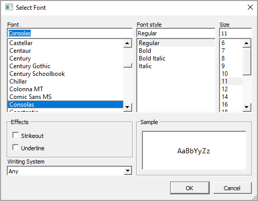
— select to display the Select Font window (shown below) where you can choose the font, font style, font size, and more for the text in the NC Editor. The default font is Consolas, size 11.

—Yes to enable or No to disable the step.
—enables automatic matching of tools when Conversational programs are loaded:
-
YES—tools in a program are automatically matched to existing tools in the Tool & Material Library.
-
NO—tools in a program must be manually matched to existing tools in the Tool & Material Library, or added though Tool Review. When NO is selected all other parameters on this tab are disabled.
—turn Autosave on or off; if Yes, programs are saved to memory at the time interval specified—it will not save to the source location of the program.
—appears when certain cutting operations are selected in the Milling Types field. When set to Yes, automatic arc blend-in and blend-out is performed. Default is Yes.
Also see Climb Milling (Left) and Conventional Milling (Right) for additional information.
—specifies whether the tool path is offset by the tool radius. Default is Yes. When enabled (Yes), the value of the Thread Diameter (set in Tool Setup) is used to determine the radius.
Enable Dual Zones
—sets a dual-zone capable machine as either a single long bed machine, or as a dual-zone machine. See Machine Parameters – General 1 in Getting Started with WinMax Mill for more information.
—enables error checking to determine whether the lead in from the current position will overlap the segment.
Enable Lead Out Error Checking
—enables error checking to determine whether the lead out from the current position will overlap the segment.
Enable Linear Thermal Compensation
—in Auto screen, specifies whether to use Linear Thermal Compensation.
Enable Pecking Retract Clearance
—enables the use of a different retract clearance for pecking operations. When set to On, the tool retracts to the height specified in the Pecking Retract Clearance parameter. When set to Off, the tool retracts to the Retract Clearance height. Default is Off.
—resets previously loaded programs when the application is started after a shutdown; default is No.
—select Yes to enable variable reset at the start of program run.
Enable Retract Z-Axis on Power Loss
—enables Z-axis retract upon power loss, when an M91 is present. See Machine Parameters – Calibration and Warm-up in Getting Started with WinMax Mill for more information.
—turn on to see simulated tool move around the part in graphics display while the machine is running; tool also shown when jogging tool near part.
—select Yes to enable tool wear monitoring. When enabled, the current cutting time is compared to the maximum cutting time set for the tool in Tool Setup Cutting Time field.
—select Yes to automatically apply a specific Surface Finish Quality (SFQ) when the tool is used in NC programs.
—select Yes to enable monitoring of an NC variable during the program run. Default is No.
—select Yes, Conversational Only, or NC Only to activate the Workpiece Coordinate System in WinMax by default for all programs, only Conversational programs, or only NC programs. With this setting enabled, WinMax controls the rotary axis positions to obtain the program tool-vector and surface contact point. Tool Center-Point Management is enabled and the control the tracks the tool tip relative to the tool piece, managing the center point at all times and effectively enabling a hidden, null transform plane around the program.
By default, WinMax uses the Unrotated Coordinate System when this parameter is disabled.
|
|
This parameter must be enabled when using the 3D DXF/Solid Model Import option. |
This parameter is system-wide and affects all programs (NC and Conversational). WORKPC TRAN is displayed in the top right-hand corner of the Part Setup and Auto Mode screens for NC and Conversational programs when Enable Workpiece Transform is enabled.
|
|
For legacy program types (non-universal) that directly command rotary axis positions, motion may not work as intended in the Workpiece Coordinate System because WinMax automatically determines the rotary axis positions. Disable this parameter if you are running Conversational programs that use Rotary Position data blocks to specify rotary axis positions or an NC program with direct rotary axis position commands. |
Refer to Workpiece Coordinate System and/or Tool Center Point Management (M128) and Tool Center Point Management Cancel (M129) for more information about the Workpiece Coordinate System.
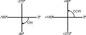
—in 3D Mold, the ending value of the angle of revolution for XY Revolved About X and XZ Revolved about Z. When determining End Angle, remember that 0º is where the contour begins and is located at the 3 o'clock position. For more information, see 3D Mold in Conversational Programming.
-
The difference between the start and end angle determines the degrees that the 2D profile revolves about the axis.
-
Start and End angles can be entered as positive or negative numbers. CCW motion is programmed as a positive number; CW motion is programmed as a negative number:

—the number of the last block in the program to be changed or run.
—the shape that is used to close the slot at the specified end point:
-
Line—flat edge connects the top and bottom edges of the slot, passing through the programmed endpoint.
-
Append Arc—rounded edge; center of semi-circle is programmed endpoint.
-
Include Arc—rounded edge; outermost edge of semi-circle is programmed endpoint.
—the last job to be run.
—determines when the endpoints of DXF segments are close enough to be considered equal (or coincident).
—select Yes to enable the pocket boundary to expand to a defined distance to remove excess corner material. Please note: This setting is only displayed when the Milling Type setting is set to Pocket Boundary.
—determines the distance the pocket boundary is expanded to remove excess material. Please note: This setting is only displayed when Expand Boundary is enabled and the Milling Type setting is set to Pocket Boundary. Only positive values are accepted.
—rotates the ATC exchange arm to its next or previous position through the Next Pos/Prev Pos softkeys.
—the number of decimal places expressed when exporting a conversational program as NC (range is 1-8); desktop version only.