Part Setup
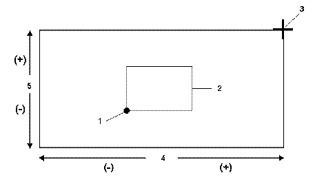
Part setup establishes the locations of part zero in X, Y, and Z relative to the machine's absolute zero. Part Zero may be located anywhere on the fixturing or the part. During machine calibration, each axis moves to its + or - travel limits. Machine zero, identified during machine calibration, is the location to which each axis moves to determine a fixed point where the X, Y, and Z axes become tangent. This value does not change after calibration.
|
1. Part Zero |
|
2. Workpiece |
|
|
3. Machine Zero |
|
|
4. X Axis |
|
|
5. Y Axis |
|
|
|
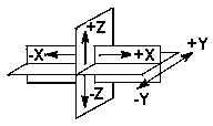
Program the axes to move within the coordinate system as shown below:
|
-X Table moves to the left |
|
+X Table moves to the right |
|
|
-Y Table moved toward the operator |
|
|
+Y Table moves away from |
|
|
-Z Spindle moved down into the part |
|
|
+Z Spindle moved up away from part |
|
|
|
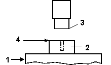
1. Table |
|
|
2. Part (Workpiece) |
|
|
3. Machine Absolute - Z Axis |
|
|
4. Tool Zero Calibration Plane |
|
|
|
Part Setup Coordinate Systems
Machine Coordinate System
The Machine Coordinate System is fixed to the machine frame and does not move when the machine axes move. This coordinate system is located at the spindle nose center when all machine axes are at their zero positions.
Unrotated Coordinate System
The Unrotated Part Coordinate System is present on a 4-axis or 5-axis machine and is located at the Workpiece Coordinate system when all the machine’s axes are at their Part Setup Zero locations. This coordinate system moves with the machine’s linear axes, but does not rotate with the rotary axes. The Unrotated Coordinate system is generally used only by NC Post Processors that do not use Tool Center Point Management.
Workpiece Coordinate System
The Workpiece Coordinate System is fixed to the physical workpiece fixtured to the table; it moves and rotates when the machine axes move.The coordinate system is fixed to the part fixtured on the machining center’s table. The Workpiece Coordinate System is typically set in the user’s CAD/CAM system or on the part drawing used for programming the tool paths.
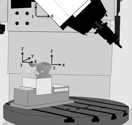
The Machine Coordinate, Workpiece Coordinate, and Unrotated Coordinate systems are shown in the figure below:
|
1. Machine Coordinate System |
|
2. Unrotated Part Coordinate System |
|
|
3. Workpiece Coordinate System |
|
|
|
|
|
|
|
|
|
Part Setup Fields
See the Field Glossary for definitions of the Part Setup fields:
|
|
|||
|
|
|
|
The fields on the Part Setup screen vary depending on machine configuration and tool calibration mode. |
|
|
Set the axis selector on the hand jog unit to 0 and turn the jog wheel to rapidly move the focus from field to field. |
Part Setup Softkeys
Part Setup contains these softkeys:
-
Work Offsets —Accesses the work coordinates G54-G59 and a set of shift values for NC programs. These are used to set multiple part zeroes for multiple parts fixtured to the table and milled consecutively using the same program.
-
Tool Setup —Accesses Tool Setup screen to enter the descriptions of tools that will be used in the part program.
-
Part Programming —Accesses fields to enter the exact description of how the part will be cut. See Part Programming in the Conversational Programming manual for more information.
-
Program Parameters —Accesses the Program Parameters screen to specify data common to all program data blocks.
-
Part Probing—Accesses the Probing parameters screen (available only with the Probing option). See Part Probing Option.
-
Store Machine Position—Sets the current axis position as a Part Zero location. The cursor location determines which axis (X or Y) will be set.
-
These are the softkeys on the second Part Setup screen, accessed with the More è softkey:
-
Stock Geometry —Accesses fields to specify the dimensions of the stock material so it displays properly in graphics.
-
Orient Spindle—Allows the spindle to be positioned for tool insertion or removal.