B
—the B end position of the move (fields are inactive for a non-rotary machine).
—in Rotary Position block, Rotary A Tilt B and Tilt B Rotary C configurations, the tilt-axis coordinate (angle) where the mill feature will be located on the part.
—In Rotary Position block, Rotary B configuration, the rotary-axis coordinate (angle) where the mill feature will be located on the part.
B—rotary-axis coordinate (angle) where the mill feature will be located on the part.
—the rotary-axis coordinate (angle) relative to Part Zero B.
—indicates if the B-axis is Clamped or Unclamped.
—the offset from true part zero. Field is available when Disable Centerlines is No in Part Setup. Program the value in order to draw the program properly on the Graphics screen.
—in Rotary A Tilt B configuration, the distance (angle) on the tilt axis between each repetition of the mill feature.
—in Rotary B configuration, the distance (angle) on the rotary axis between each repetition of the mill feature.
—the offset for the B axis, to be added to the B dimension in the data block.
—choose Black or White background color for the graphics display.
—the communication speed rate.
—the width of the beam based on + and - trigger points (laser tool probe only). This field is updated after running the Determine Laser Beam Offset cycle. It may be adjusted by the user to optimize performance.
—the direction of the tool path while the 3D Mold part is being machined:
-
No—causes the tool to machine in one direction, based on the direction of the contour definition.
-
Yes—causes the tool to machine in both directions without retracting the tool until the entire contour is complete.
|
|
|
1 Yes |
|
|
2 No |
|
|
|
|
|
|
|
|
|
—the size of the blank character (space). Leave at zero to use the default spacing for the selected font.
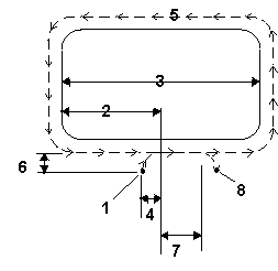
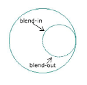
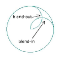
—the distance from the entry point of the part surface and the Z plunge point where the tool enters the work piece. This field is used in milling circles, frames, and ellipses; it is also used in contours with Milling Type set to Left/Right or Profile Left/Profile Right and Enable Blend Moves set to Yes.
-
The default is 0.1181 inches (3 mm).
-
The range is 0 through 99.999 inches (0 through 2539.997 mm).
—the distance the tool travels past the entry point before it is withdrawn from the part. This field is used in milling circles, frames, and ellipses; it is also used in contours with Milling Type set to Left/Right or Profile Left/Profile Right and Enable Blend Moves set to Yes.
-
The default is 0.1181 inches (3 mm).
-
The range is 0 through 99.999 inches (0 through 2539.997mm).
|
1. Start Point |
|
2. 1/2 X length |
|
|
3. X length |
|
|
4. Blend offset |
|
|
5. Tool path |
|
|
6. Blend offset |
|
|
7. Blend overlap |
|
|
8. End point |
—the type of blend move to make at the beginning and end of the threading operation. Choices are line, ramp, arc, helix:
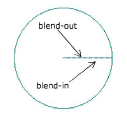 Line |
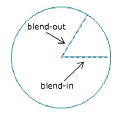 Ramp |
 Arc |
 Helix |
—the block number for this operation. The system determines the number by the position of this data block in the program.
—in the DRO, the block number and type for Conversational programs. Displays 5 current blocks for NC programs (2 previous, current, 2 next).
—when toggled ON in NC Editor Settings, NC codes which follow the Ignore (/) character are skipped.
—the stock border dimension in Stock Geometry (field is available only when Manual Border Sizing is set to YES).
—the pause in seconds before the tool retracts at the bottom of a Bore operation. This parameter is not used for NC programs.
-
The default is 1.0 seconds.
-
The range is 0 through 20 seconds.
—the distance and retract angle the boring tool moves away from the part surface at the end of the boring cycle. Used only when a Bore Orient data block is included in the part program.
—the output location for BPRINT and DPRINT formatted data.
—the file path if BPRINT and DPRINT data will be output to a file.
—the amount of deviation from the tool length programmed in the Tool Cal Length field in Tool Setup.