Tool Setup
Use the Tool Setup screen to describe the tools that will be used for the part program. You can access Tool Setup from several screens by using the Tool Setup softkey.
To review all tools currently programmed, go to the Tool Review screen.
|
|
When running a previously created part program, Tool Setup must be carefully checked to be certain the tools described for the old program match the tools planned for the new program. If a tool breaks or is not available when running a previously created part program, the Tool Setup information must be changed. |
Tool Setup Fields
See the Field Glossary for definitions of the Tool Setup fields:
|
|
|||
|
|
|||
|
|
|
|
The fields on the Tool Setup screen vary depending on machine configuration, tool calibration mode, and tool type. |
|
|
Set the axis selector on the hand jog unit to 0 and turn the jog wheel to rapidly move the focus from field to field. When the focus hits the tool number, it scrolls to the next or previous tool for most tools. |
Tool Setup Softkeys
Softkeys perform the following functions:
-
Delete Tool—Deletes all program settings for the tool number entered in the Tool Field, for a Manual tool. If the Tool and Material Library software option is enabled and the tool is in Spindle or Auto, this softkey is not active.
-
Part Setup — Accesses Part Setup screen.
-
Part Programming —Accesses fields to enter the exact description of how the part will be cut.
-
Tool Offsets—Available only for NC programs. The tool length offsets appear on the screen. Tool offsets are tool lengths used to compensate tool length without altering the NC program.
|
|
Tool offsets are not saved with the NC program. |
-
Use the Positive Tool Length Compensation (G43) or Negative Tool Length Compensation (G44) codes. A G49 code specifies tool offset cancel. An H00 also cancels an offset.
-
The G43 and G44 codes set a mode of operation within the program that is in effect until a G49 or H00 is used. If an H code is used without a G43 or G44, in effect, the value stored in the tool length offset table is used as the calibrated tool length.
-
If a zero is entered for the Tool Offset value (Tool Offset H Table), the control uses the Tool Offset value entered in Tool Setup for the tool length.
-
If a value greater than zero is entered for the Tool Offset value (Tool Offset H table), the control replaces the value set in Tool Setup with the Tool Offset H Table value.
-
The four keyboard arrows, Page Up, and Page Down keys scroll through the 01 to 200 offsets.
-
When the Store Machine Position softkey is pressed, a negative Z value reflecting the Z axis machine position is entered on the screen.
-
Tool Home—Allows you to move the tool quickly away from the part. Using this softkey after Tool Calibration is much faster than pressing the axis jog buttons on the jog unit. Press this softkey and then press the Start Cycle button to move the spindle to the change height.
-
Set Tool Zero (Zero Calibration mode)—stores the Z-axis position of the tool tip when at workpiece or gauge block plane. To use this softkey, carefully jog the tool in the spindle down to the top of the part or to the fixture defined at the Tool Calibration point and then press the softkey. The system stores the position of the tool into the current part program and the number appears in the Zero Calibration field on the Tool Setup screen. This can also be accomplished by pressing the Store Position button on the jog unit. On the screen the part display for “Z” changes to zero. In Zero Calibration mode, all tools used in a part program will need to be calibrated to the same plane.
|
|
A warning message is displayed if the edited tool is not the tool in spindle. Select OK to store the current position for the tool that is being edited. Select Cancel if you do not want to set tool zero for that tool. |
-
Set Length Using Touch-Off Device (Absolute Tool Length mode)—stores the tool length when using a gauge or other touch-off device. For a gauge, carefully jog the tool in the spindle down to the top of the gauge and select the softkey. The system stores the tool length in the Tool Cal Length field.
|
|
This softkey is active when the following is true:
|
-
Set Tool Zero Using Gauge Block (Zero Calibration mode; Probing only)—stores the Z-axis position of the tool tip when using a gauge block into the Zero Calibration field and marks the tool as probed so it can be used in Part Probing. To use this softkey, carefully jog the tool in the spindle down to the top of the gauge at the Tool Calibration plane and press the softkey.
|
|
This softkey is active when the following is true:
|
Second set of Tool Setup softkeys:
-
Advanced Tool Settings —set Tool Geometry, Feed and Speed, Surface Finish Quality, and other tool information.
-
Change Tool Number —Allows you to change the tool number for the current tool displayed.
-
Tool Probing—Accesses the Probing Parameters, see Program Parameters. Probing is available only with BMCs.
-
Program Parameters —Accesses the program parameters.
-
Part Program Tool Review —Accesses the tool review screen.
-
Tool Measurement Settings (Absolute Tool Length mode)—accesses the Tool Measurement screen where touch-off device height is set.
Advanced Tool Settings
Basic tool information is stored in Tool Setup and additional information can be set in the Advanced Tool Settings screens. Tool Geometry, Feed and Speed information, SFQ, and other tool information are set in the Advanced Tool Settings screen.
|
|
Advanced Tool Settings are optional; it is not necessary to adjust these settings in order to run part programs. They are available to simplify programming and increase program efficiency. |
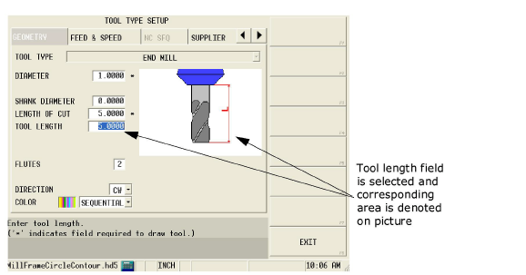
Tool Geometry
Tool dimensions are set in the Geometry tab. Fields denoted with a * are required in order to draw a tool in Solid Graphics; however, these fields are automatically populated with information from Tool Setup, as ratio of entered diameter. A picture of the tool is displayed, and when a field is selected, that area on the picture is denoted.
Most fields on the Geometry screen correspond to tool type; see the following table for information about these fields. Additional Geometry fields are:
The following table provides the tool-type specific fields:
|
|
|||||||||||||||||||
|---|---|---|---|---|---|---|---|---|---|---|---|---|---|---|---|---|---|---|---|
|
Drill |
X |
X |
X |
X |
X |
X |
|
|
|
|
|
|
|
|
|
|
|
|
|
|
Tap |
|
|
X |
X |
|
|
X |
X |
|
|
|
|
|
|
|
|
|
|
|
|
Boring head |
X |
X |
X |
X |
|
|
|
|
X |
|
|
|
|
|
|
|
|
|
|
|
End Mill |
X |
x |
x |
x |
|
|
|
|
|
|
|
|
|
|
|
|
|
|
|
|
Face Mill |
x |
x |
|
x |
|
|
|
|
X |
X |
X |
|
|
|
|
|
|
|
|
|
Ball End Mill |
X |
X |
X |
X |
X |
|
|
|
|
|
|
|
|
|
|
|
|
|
|
|
Back Spotface |
X |
X |
X |
X |
X |
|
|
|
|
|
|
|
|
|
|
|
|
|
|
|
Probe |
X |
X |
|
X |
|
|
|
|
|
|
|
X |
|
|
|
|
|
|
|
|
Gun Drill |
X |
X |
X |
X |
X |
X |
|
|
|
|
|
|
|
|
|
|
|
|
|
|
Center Drill |
X |
X |
|
X |
X |
|
|
|
|
|
|
|
X |
X |
X |
X |
|
|
|
|
Chamfer Mill |
X |
X |
|
X |
X |
|
|
|
|
X |
|
|
|
|
|
X |
|
|
X |
|
Bull Nose Mill |
X |
X |
X |
X |
X |
|
|
|
X |
|
|
|
|
|
|
|
|
|
|
|
Ream |
X |
X |
X |
X |
X |
|
|
|
|
|
|
|
|
|
|
|
X |
|
|
|
Spot Drill |
X |
X |
|
X |
X |
|
|
|
|
|
|
|
X |
|
|
|
|
|
|
|
Forming Tap |
|
X |
X |
X |
|
|
X |
X |
|
|
|
|
|
|
|
|
|
|
|
|
Counter Bore |
X |
X |
X |
X |
X |
|
|
|
|
|
|
|
|
|
X |
X |
|
|
|
|
Counter Sink |
X |
X |
|
X |
X |
|
|
|
|
|
|
|
X |
|
|
X |
|
|
|
|
Keyseat Mill |
X |
X |
X |
X |
X |
|
|
|
|
|
|
|
|
|
|
|
|
X |
|
|
Thread Mill Single Cutter (SC) |
X |
X |
|
X |
X |
|
|
|
|
|
|
|
|
|
|
|
|
|
|
|
Thread Mill Multi Cutter (MC) |
X |
X |
X |
X |
X |
|
|
X |
|
|
|
|
|
|
|
|
|
|
|
|
Taper Radius End Mill |
X |
|
X |
X |
X |
|
|
|
X |
|
|
|
X |
|
|
X |
|
|
|
|
Corner Round Mill |
X |
X |
X |
X |
X |
|
|
|
X |
|
|
|
|
|
|
X |
|
|
|
|
Dove Tail Mill |
X |
X |
X |
X |
X |
|
|
|
|
|
|
|
X |
|
|
|
|
X |
|
|
Engraving Mill |
X |
X |
|
X |
|
|
|
|
|
|
|
|
X |
|
|
X |
|
|
|
|
|
Tip Diameter is used to calculate Milling Type offset for Chamfer Mill, Corner Round Mill, and Taper Radius End Mill. |
|
|
When Shank Diameter, Length of Cut, and Tool Length are set as a ratio of the diameter, values will be automatically recalculated if the diameter changes or until a user-defined value is entered. |
|
|
When used in a Thread Milling cycle, the Length of Cut and Pitch are used to calculate the number of passes in the cycle. |
Feed and Speed
|
|
Feed and Speed in Advanced Tool Settings is available only with the Tool and Material Library option. |
Feed and Speed settings are carried over from Tool Setup or can be specified in the Feed and Speed tab for specific tool and material combinations in a part program. Choose one of the materials from the work material list for a specific tool and enter the feeds and speeds for both roughing and finishing for that tool and work material combination. This information is saved in the Tool and Material Library and can be utilized in future part programs without re-entering the speeds and feeds: When the Program Parameters for a part program specify a work material, the tool number will recall the feed and speed for that material.
|
|
Regardless of the material set in the Feed and Speed tab, the main Tool Setup screen will always display feeds and speeds for “Unspecified” material. |
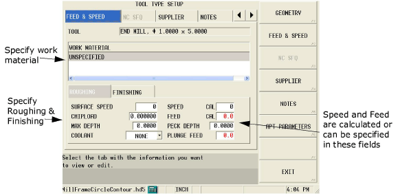
Roughing and finishing tool parameters can be specified.
See the Field Glossary for definitions of the Feed and Speed fields:
Feed and Speed Calculations
The WinMax software automatically performs tool feed and speed calculations for each tool programmed in Tool Setup. The calculations are carried over to each data block in the part program using the programmed tool.
The software uses data to perform the calculations from these Tool Setup fields: Diameter, Speed (RPM), Surface Speed (FPM) or (MPM), Flutes, and Feed/Flute (Tooth). Feeds and speeds are related using the following formulas: Speed Formulas and Feed Formulas .
Calculated values are carried forward to the Mill Feed field and Speed (RPM) field for milling and holes data blocks. You can override automatically calculated values in a data block by inserting a user defined value. If you manually change a calculated value in Tool Setup, you will be prompted to update feeds and speeds for the part program data blocks.
|
|
For fields that display truncated decimal point values, you may view the non-truncated value by pressing and holding the CTRL key and pressing the period (.) key. |
Speed Formulas
The WinMax software uses these formulas to automatically calculate the spindle speeds:
Metric Mode:
Surface Speed x 100
![]()
English Units:
![]()
|
|
If the calculated RPM exceeds the maximum spindle RPM entered in Machine Specifications, the value appears in red font color. |
|
|
If you enter the Surface Speed (fpm) value, the Speed (RPM) value will be calculated for you. If you enter the Speed (RPM) value, the Surface Speed (fpm) value will be calculated for you. In some cases, calculation rounding may slightly alter a calculated value. For example, if you enter a value of 7000 RPM for the Speed field in Tool Setup for a Drill operation, the calculated value for Surface Speed is 458 fpm. However, if you enter a Surface Speed of 458 fpm in the Surface Speed field, the calculated value for Speed is 6997 RPM. |
Feed Formulas
For Milling data blocks, specify the number of flutes for the tool in the Flutes field.
The software uses the following formula to calculate the Mill Feed:
![]()
For Holes operations, flutes are not specified for the tool.
The software uses this formula to calculate the Mill Feed:
![]()
|
|
If the calculated feedrate exceeds the maximum contouring feedrate for the machine, an error is generated during the program run. |
NC SFQ
|
|
NC SFQ in Advanced Tool Settings is available only with the NC/Conversational Merge option. |
Surface finish quality in NC programming is set in the NC SFQ tab of Advanced Tool Settings. Change Enable Tool SFQ to YES and adjust the Tool SFQ value. This automatically sets the SFQ value whenever the tool is used in NC programming and will override the SFQ value set in Program Parameters or with the G05.3 setting.
See the Field Glossary for definitions of the NC SFQ Fields:
Supplier
|
|
Supplier in Advanced Tool Settings is available only with the Tool and Material Library option. |
The Supplier tab is optionally used to store information about tool supplier and orders in memo-type fields.
Notes
|
|
Notes in Advanced Tool Settings is available only with the Tool and Material Library option. |
The Notes tab is used to store notes and miscellaneous information about a tool in a memo-type field.
Edit Apt Parameters
The Edit Apt Parameters fields are defined as follows:
-
Tool—displays the tool number and type entered on the Tool Setup screen. This field cannot be edited. To change tools, go to Tool Setup.
-
NC Gear Range—define the spindle gear range. 0 = Low; 9 = High.
-
NC Tool Number—indicate the starting tool in the tool changer. The range is 0 to 999.
-
NC Diameter Offset—indicate the tool diameter to be used for cutter compensation. This field is used for posting only. This will not affect a file that is saved as an ISNC file.
|
|
If Cutter Comp is selected from the Output Tool Path As field on the Post Processor Configuration screen, the value in the NC Diameter Offset field will be put into the APT file. This value will refer to the tool diameter offset on the target machine. If Centerline is selected from the Output Tool Path As field, then the value entered in the NC Diameter Offset field will not affect the APT file. |
Change Tool Number
The Change Tool Number softkey allows you to change the number of an existing tool or copy an existing tool and give it a different number while retaining the tool with the same number.
To change the Tool Number or create a copy of a tool, display the tool in the Tool Setup screen. With the cursor in the Tool Number field, select the More softkey to display the next softkey menu. Select the Change Tool Number softkey. The Current Tool Description and New Tool Number fields are displayed. Type the new number into the New Tool Number field and select one of the following softkeys:
-
Change Tool Number—changes the number of the tool to the new Tool Number. The old tool number is simply changed to the new number. If the new tool number is already assigned to another tool, then the tool numbers are swapped. If the Tool Library option is enabled, the tool number is also updated in the spindle or ATC.
-
Copy Tool—adds a new tool that is identical to the Current Tool Description.
If the New Tool Number is not in the current program or Tool & Material Library, the current tool is copied to the New Tool Number. If the New Tool Number is already used in the current program or Tool & Material Library, a prompt appears that the New Tool Number selected will be replaced with a copy of the current tool.
More Information Online
For more information about the WinMax Tool Setup function, visit the Hurco Mill Training Course page on hurco.com/connect and scroll down to the Tool Setup video.