Rotary Part Setup
|
|
Follow this link to the Hurco website to view a 5-Axis Part Setup video demonstration: Video Demonstrations at www.hurco.com Scroll to the bottom of the page and select the video to download. Internet connection is required. Viewing the video on a machine may cause the system to slow during viewing and for a short period of time after the video is closed. For best results, the video should be played when there is no other activity (for example, programming or cutting a part) on the machine, and the video window should be closed after viewing. The video may also be viewed from a PC at www.hurco.com. |

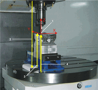
Ensure that the B-axis angle is at zero degree when measuring Z Table Offset, Offset Z, and Zero Calibration fields for 5-axis machining.
For conversational programs, B-axis Part Setup Offset must be zero degree.
|
1. Workpiece Coordinate System |
|
2. Zero Calibration (positive value) |
|
|
3. Offset Z (positive value) |
|
|
4. Z Table Offset (positive value) |
|
|
|
|
|
|
Rotary Part Setup for Zero Calibration mode
See Tool Calibration Modes for more information about tool calibration.
In addition to standard Part Setup fields, Part Setup for rotary programming in Zero Calibration mode includes part zero for the rotary axis and the rotary centerline fields.
|
|
Manually type the values directly into the Part Setup fields, or use the jog unit to set the values. Follow these steps to use the jog unit to enter the Part Setup values:
|

Zero Calibration Rotary Centerline Calculation
Hurco recommends automatically calculating the rotary centerline. Use the following steps:
-
Enter Part Zero X and Part Zero Y field values, either manually or by using the jog unit to store the machine position.
-
Place the cursor in the Part Zero X, Part Zero Y, or Offset Z field to make the Calculate Rotary Offsets softkey available.
-
Select the Calculate Rotary Offsets softkey. The machine automatically calculates the values for the rotary centerline fields.
|
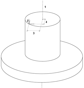
1. Center of cylindrical part and center of rotary table |
|
2. Part Zero |
|
|
3. A Centerline Y |
|
|
4. A Centerline Z |
|
|
|
|
|
|
|
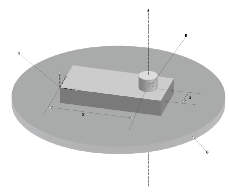
1. Part Zero |
|
2. X Center |
|
|
3. Y Center |
|
|
4. Rotary Centerline |
|
|
5. Rotary Centerline |
|
|
6. Rotary Table |
|
|
When the part is fixtured to the center of the rotary-axis table, the rotary centerline is the Y-Z center point of the part. |
