Part Programming
Part Programming is the process of entering data, often from a blueprint, into program data blocks to create a part.
Data blocks appear in numerical order as they are created.
To create a Conversational Part Program:
-
Press the Input console key to display the Input screen. The Input screen allows you to access setup functions including Import Functions, Tool Setup, and Program Parameters. See Input Model for more information.
-
Enter machining operation information in the Part Setup and Tool Setup functions. This information is stored within data blocks describing each operation to be performed. Create and access the data blocks through the Input screen.
-
Select the Part Programming softkey to begin programming. The system displays either the first block of an existing program or a New Block screen for new programs.
Data blocks can be managed with the following programming operations:
-
Access softkeys to create a new data block or edit an existing data block in the Input screen.
-
View a list summarizing a part program's data blocks on the Program Review screen. See Review Mode for more information.
-
View the current program's tool list on the Tool Review screen. Refer to Part Program Tool Review for more information.
-
Use the Insert Block Before softkey to Insert a new data block between two sequentially numbered blocks. The data blocks following the inserted block are automatically renumber.
-
Holes blocks contain operations, and Mill Contour blocks contain segments.
Part Programming softkeys access the following options:
-
Position—Insert instructions to move the tool away from the part (or fixture), or to stop a program. A Position block is most often used to move the table to an X-Y location and is normally used at the end of the program and at any time the tool must be moved to the Z Top position of the Safety Work Region. See Position Data Block for more information.
-
Holes—Select Drill, Tap, Bore and Ream drilling operations, and Back Spotface and Bolt Circle hole drilling. The locations of these holes on the part can be specified using the Locations operation, and the holes can also be programmed in a Bolt Circle pattern. See Holes Operations for more information.
-
Milling—Program milling operations. See also Lines and Arcs (Mill Contour), Mill Ellipse , Mill Frame, Mill Face, Mill HD3 Lettering, and Swept Surface Parameters. Special milling blocks Triangle, Diamond 1 Face, Diamond 2 Faces, and Hexagon are accessed with the Special è softkey, see Insert Pockets for more information.
-
Patterns—Repeat or modify a sequence of one or more data blocks. A program sequence can be repeated in a rectangular, linear, angular, or rotated pattern or at specified locations. This operation is also used to scale or mirror a programmed part. See Patterns Operations for more information.
-
Miscellaneous—Access these softkey functions:
-
Graphics Off and ON; see Graphics On/Off.
-
Change Parameters; Change Parameters.
-
Change Part Setup; see Change Part Setup.
-
Machine Function; see Machine Function.
-
Probe Part Setup; see Probe Part Setup Data Block.
-
Lube Cycle; see Lube Cycle.
-
Comment; see Comment Block.
-
Insert; see Insert Block.
-
Tool Monitoring (Probing); see Tool Quality Monitoring.
-
Part Inspection; see Part Quality Verification.
-
Tool Optimize On and Off; see Tool Change Optimization.
-
-
NC Program Call—Access an NC program from within the conversational program with this softkey. See NC/Conversational Merge.
-
Rotary and Transform Planes—Accesses the Rotary New Block menu where you can access the Rotary Position, Milling, and Patterns, and Parameters blocks, as well as the Transform Plane and Transform Plane Groups blocks. See Rotary for more information.
Block Layout
The layout of most data blocks includes the part geometry at the top of the screen with the tool information below it, as in the following example:
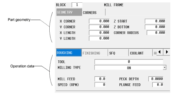
Operation Data
Information about block execution, such as tool, cutter compensation, pocketing, roughing, finishing, coolant and surface finish quality is entered on the bottom part of the data block. Fields are displayed on tabs for Roughing, Rest, Finishing, SFQ, Coolant and Allowances. The tabs and fields displayed are dependent on the block, machine type/configuration or software options installed:
Roughing tab
This tab contains the tool information for the roughing pass.
-
Tool—the tool used for the roughing pass.
-
Milling Type—the type of cutting operation.
-
Pocket Type (appears when Milling Type is Pocket Boundary)—the pocket type: Inward, Outward, ADP Zigzag, or ADP 1-Way.
-
Mill Feed—the axis feedrate. Value initially displayed has been calculated by the control and can be retained or changed to a different value.
-
Speed (RPM)—spindle speed for the roughing tool. This value is carried over from Tool Setup, but can be overridden here by typing a value in the field.
-
Step Over (%)— the percentage of tool diameter engaged in each cutting pass in a pocket milling operation. Appears when Pocket Boundary Milling Type is selected with Inward or Outward Pocket Type.
-
Peck Depth—the maximum depth to be cut in one pass. If the total depth is greater than this value, multiple cutting passes occur. Entering a zero (0) value causes the total programmed depth to be cut in one pass of the tool.
-
Plunge Feed—the feedrate for the tool moving from Z Start to Z Bottom.
-
Radial Peck Count (appears only in a Mill Thread block)—the number of radial pecking passes. See Radial Pecks for more information.
-
Radial Peck Depth (appears only in a Mill Thread block)—the incremental distance from the final cut. See Radial Pecks.
Rest tab
This tab appears only when the Milling type is Pocket Boundary and the Pocket Type is ADP Zigzag or ADP 1-Way (UltiPockets option required). This tab is used to specify the tool information for the rest milling pass - to clear out remaining material from corners when pocketing.
-
Tool—the tool used for the rest milling pass.
-
Pocket Type—the pocket type: ADP Zigzag or ADP 1-Way.
-
Mill Feed—the axis feedrate. Value initially displayed has been calculated by the control and can be retained or changed to a different value.
-
Speed (RPM)—spindle speed for the rest milling tool. This value is carried over from Tool Setup, but can be overridden here by typing a value in the field.
-
Peck Depth—the maximum depth to be cut in one pass. If the total depth is greater than this value, multiple cutting passes occur. Entering a zero (0) value causes the total programmed depth to be cut in one pass of the tool.
-
Plunge Feed—the feedrate for the tool moving from Z Start to Z Bottom.
Finishing tab
This tab contains tool information for the finishing pass.
-
Tool—the tool used for the finishing pass.
-
Milling Type—the type of cutting operation. This value is carried over from the Roughing tab and cannot be changed.
-
Pocket Type (appears when Milling Type is Pocket Boundary)—the pocket type for the finish pocketing operations: Inward or Outward.
-
Mill Feed—the axis feedrate. Value initially displayed has been calculated by the control and can be retained or changed to a different value.
-
Speed (RPM)—spindle speed for the finishing tool. This value is carried over from Tool Setup, but can be overridden here by typing a value in the field.
-
Plunge Feed—the feedrate for the tool moving from Z Start to Z Bottom.
SFQ tab
This tab is used to specify the surface finish quality for the roughing pass and finishing pass.
The default SFQ for roughing is 80 and finishing is 20. Recommended values are:
|
SFQ |
Desired Result |
|---|---|
|
1-20 |
High precision parts / finishing |
|
21-79 |
Good surface quality / finishing, semi-finishing |
|
80-100 |
High throughput / roughing |
Coolant tab
The Coolant tab appears in Milling and Holes data blocks. This tab allows for overriding the tool’s default Tool Setup coolant settings, including overrides to program coolant with Air Through Spindle (ATS). Auxiliary coolant control can be programmed in this tab.
The override coolant controls are available for roughing and/or finishing passes.
-
Override Tool—indicates if the default Primary and/or Secondary coolant (or ATS) setting for the tool will be overridden by the setting in this block.
-
Coolant—available only when Override Tool is set to YES. Indicates coolant type to which the override applies in this block: OFF (disables all coolant types), PRIMARY, SECONDARY, BOTH, or ATS.
-
Auxiliary—indicates if the coolant mapped to an auxiliary output is activated. NO CHANGE indicates that the auxiliary coolant setting (activated or not) prior to this block does not change in this block. ON activates auxiliary coolant in this block and NO deactivates it in this block.
|
|
Any coolant other than auxiliary applied by an earlier M code is replaced by coolant settings in the data block, regardless of whether overrides are applied here or not. |

Allowances tab
This tab appears when Stock Allowance mode is set to Data Blocks in Program Parameters, Milling 1 tab. See Program Parameters in Getting Started with WinMax Mill. This allows the stock allowance to be set in the data block rather than using a global value from Program Parameters.
Set the stock allowances left by the roughing pass:
-
Finish XY—specifies the stock width to be left by the roughing pass.
-
Finish Z—specifies the stock depth to be left by the roughing pass.
When the cursor is in the Finish XY or Finish Z field, the following softkeys appear:
-
Copy Allowances from Parameters—copies the values for Finish XY and Finish Z from Program Parameters.
-
Clear Allowances—zeros out the values in the Finish XY and Finish Z fields.
Select Tool from List
Use the following steps to select a tool using the Select Tool From List softkey:
-
In a program block screen, place the cursor in the Tool field and choose the Select Tool From List softkey.
-
Locate the desired tool using one of the following methods:
-
Scroll through the list of tools and select the desired tool to highlight it.
-
Begin typing the number of the desired tool. A pop-up box will appear when the first digit is entered; enter the entire number and select OK to jump to that tool number in the list.
-
-
Select the Select Tool softkey, which enters the tool into the data block or segment.
|
|
If Tool Type Checking is enabled, only tools that are suitable for the programmed operation can be selected. |

|
|
Check the Display Tool Notes checkbox to view the Notes for each tool. Notes can be entered in Part Program Tool Review and Advanced Tool Settings when the Tool & Material Library option is installed. |

|
|
The Select Tool list displays in the sort order most recently used, when accessed via any screen - data blocks, Tool Management, or Tool Setup. |

Temporary Parameter Change
For some programs, you may want to insert a temporary parameter change block between data blocks.
-
Display the data block for which the parameter change will first be used.
-
Select the Insert Block Before softkey. The New Block screen appears.
-
Select the Miscellaneous softkey. Choose the Change Parameter Softkey.
See Change Parameters and Change Part Setup for more information.
Automatic Calculations
The WinMax AutoCalc feature enables the system to calculate certain dimensions automatically after sufficient data has been programmed. Leave a data field blank to automatically calculate the value for that field. After sufficient data is entered in the other fields, the system automatically fills in the blank data field(s) and displays “CAL” next to those field(s).
The screen displays a Store Calculated Value softkey for editing a field with a calculated value. Select this softkey or the Enter key to store the displayed value into the part program. Do not re-enter the data, i.e., 8.9199; the data is actually 8.9199xxx and will be calculated as such when entered with the softkey or Enter key.
If you enter a value and later decide to let the control calculate the data, clear the entered value by following these steps:
-
Use the Arrow keys or the touchscreen to select the parameter where the automatic calculation is needed.
-
Press the C (Clear) console key or the Delete key on the keyboard.
-
Press the Enter key. The calculated value is displayed (if the field remains blank, additional data must be entered so the control can calculate the value).