Mill Frame
The Mill Frame data block supports the creation of frames with or without uniform corners.
To start a new Mill Frame block:
-
From the Input screen, select the Part Programming softkey or icon.
-
Select the Insert Block Before softkey.
-
From the New Block screen, select the Milling softkey.
-
From the New Block (Milling) screen, select Frame. Mill Frame screen opens.
The Mill Frame block fields appear on two tabs: Geometry and Corners. The frame geometry parameters are entered on the Geometry tab. Corner Radius specifies the radius of the reference corner. Use this field if all four corners of the frame will have the same radius.
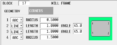
To program unique corners (with different radii), parameters are set on the Corners tab. Select Line or Arc for each corner, and specify a radius for arcs, or length and angle for lines. If the corner should have neither, geometry should be left as an arc with radius of 0.00, which is the default.
|
|
If all four corners of the frame should have the same radius, the Corners tab does not need to be used; instead use the Corner Radius parameter on the Geometry tab. |
|
|
Specifying a value in the Corner Radius field will reset all of the corners set as Arcs in the Corners tab to that radius. If you are creating unique corners, do not use the Corner Radius field. |
The Field Name Glossary contains definitions of all WinMax fields. The fields listed below appear on the Mill Frame screen. Fields displayed on screen may vary according to machine type, configuration, parameter settings, and/or settings in other fields.
|
|
|||
|
|
|||
|
|
|||
|
|
|||
|
|
|||
|
|
|
||
|
|
|
|
|
For Rotary Frame, see Rotary Frame - Universal in the Rotary manual. |
Mill Frame Example
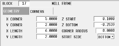
The sample data in the fields above create the following frame.
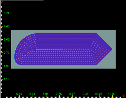
In this example, Milling Type is ON. Machine movement is:
-
Tool moves at Rapid Traverse rate to Z Start.
-
Tool moves at Plunge Feed rate to Z Bottom at the mid-point of the bottom side of the frame (because Start Side is Bottom).
-
When the tool reaches Z Bottom, milling occurs with the center of the tool along the contour (Milling Type On), moving clockwise around the frame until milling is complete.
-
Tool retracts at Rapid Traverse rate to the plane.
|
|
Cutter compensation, set in the Milling Type field, determines the compensation applied to the tool path. See Cutter Compensation (preliminary) for more information. |
|
|
Pecking is the use of multiple cutting passes to optimize tool operation. See Pecking for more information. |
|
|
To use pocketing with Mill Frame, the UltiPockets option must be installed. See UltiPockets for more information. |
|
Follow this link to hurco.com/connect to view Mill Frame video demonstrations: Mill Frame video demonstrations on hurco.com/connect Scroll down on the page and select the Intro 3 or Intro 4 Mill Frame video to download. Internet connection is required. |