Mill Thread
The Mill Thread data block mills a part with internal or external threads. Milling can be clockwise or counterclockwise, and occur from top to bottom or bottom to top.
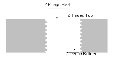
Thread Direction Down
The following diagram shows the Z positions, and the arrows indicate tool movement when the Thread Direction is Down. In this case, the tool moves at rapid feedrate to the Z Plunge Start position, then feeds to the Z Top position. The tool mills down to the Z Bottom position. It then moves at rapid feedrate out of the hole to Z Plunge Start + Z retract clearance height (set in Program Parameters).
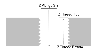
Thread Direction Up
The following diagram shows the Z positions, and the arrows indicate tool movement when Thread Direction is Up. In this case, the tool moves at rapid feedrate to the Z Plunge Start position, then feeds down to the Z Bottom position, and mills up to the Z Top position. The tool then moves at rapid to Z Plunge Start and retracts to the Z retract clearance height (set in Program Parameters).
To access the Mill Thread block:
-
From a New Block screen, select the Milling softkey.
-
Select the More softkey twice.
-
Select the Thread softkey. The Mill Thread block opens.
Thread geometry is set in the Thread tab. Specify the radius, TPI/Pitch, inside or outside threads, start angle, and any taper angle.
Thread location is set in the Location tab. Specify the X and Y centers, the Z plunge start point, thread top and bottom locations, and the threading direction.
Cutting information is set in the Process tab. Specify cutter compensation, blend type, and center start.
When using a single-cutter thread mill, the Taper Angle field appears in the Thread tab. External threads must have a positive taper angle and internal threads must have a negative taper angle:
 -10° Taper with Internal Threads |
 10°Taper with External Threads |
The Field Name Glossary contains definitions of all WinMax fields. The fields listed below appear on the Mill Thread screen. Fields displayed on screen may vary according to machine type, configuration, parameter settings, and/or settings in other fields.
|
|
|||
|
|
|||
|
|
|||
|
|
|||
|
|
|||
|
|
Radial Pecks
The Radial Peck feature can be used when more than one cutting pass is required, such as with harder materials.
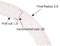
Enter an incremental distance from the final cut in the Radial Peck Depth field, and enter the number of passes in the Radial Peck Count field. Milling occurs as follows:
-
Orientation Outside—milling begins at (radius) + (Radial Peck Count x Radial Peck Depth) position, and proceeds inward for the number of passes (count) specified, to the final radius cut.
-
Orientation Inside—milling begins at (radius) - (Radial Peck Count x Radial Peck Depth) position, and continues outward in the number of passes (count) specified, to the final radius cut.
For example:
Radius = 2.0 Radial Peck Count = 10 Radial Peck Depth = .05 Orientation = Inside
Milling begins at 1.5 |
 |
If Radial Pecking is not desired, set Radial Peck Count to 1 (default).