Tool Quality Monitoring
Tool Monitoring is available to automatically monitor calibrated tools and detect breakage or wear. The software compares the current tool dimensions to the calibrated dimensions stored in Tool Setup for the programmed tool. If the current dimensions deviate from the defined tolerance programmed in the tool monitoring menus, the tool is defective.
This section describes the ways to perform Tool Monitoring:
Probe Tool Monitoring Data Block
Automatic Tool Monitoring Parameter
Probe Tool Monitoring Data Block
It is possible to program a spare tool (Sister Tool) to automatically replace a defective monitored tool. If a Sister Tool is not programmed, or if there is no ATC, axis motion stops and the following message appears on the screen:
To access the Probe Tool Monitoring data block, follow this softkey sequence from the Input screen:
-
Select Part Programming.
-
Select Miscellaneous.
-
Select More.
-
Select Tool Monitoring (Probing).
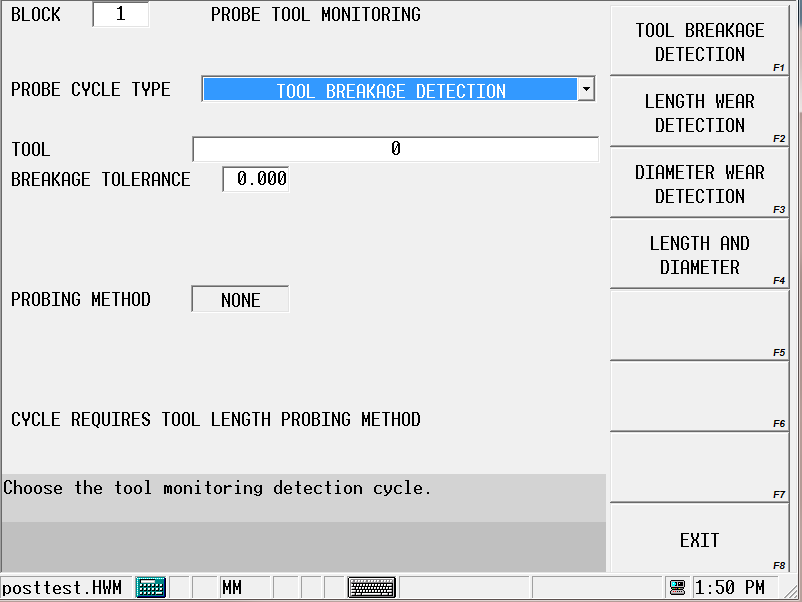
From the Probe Tool Monitoring screen, select the type of measuring cycle by selecting the appropriate softkey. The measuring cycles are described in the following sections.
|
|
As with any data block, use the Insert Block Before and Delete Block softkeys available for each measuring data block to add and delete measuring cycles from the program. |
Tool Breakage Detection
Tool Breakage Detection monitors the tool for breakage. Follow these steps to program a Tool Breakage Detection Cycle:
-
From the Probe Tool Monitoring screen, select Tool Breakage Detection in the Probe Cycle Type field.
-
Enter the tool to be monitored, in the Tool field. The tool must be programmed in Tool Setup, and it must be probed.
-
If desired, adjust the Speed (RPM) value.
-
Enter the Breakage Tolerance. This is the amount of deviation from the tool length programmed in the Tool Cal Length field in Tool Setup.
When the data block is executed in the part program, the current tool length is measured and compared with the Tool Cal Length/Zero Calibration in Tool Setup.
The software monitors the tool and determines if the tool is within the Breakage Tolerance. If the tool is shorter than the programmed tolerance, the tool is broken. If the tool is broken, the software checks for a spare tool.
-
If a Sister (spare) Tool has been entered in Tool Setup for this tool, axis motion stops and a tool change automatically occurs.
-
If there is no Sister Tool programmed for this tool, or if there is no ATC, axis motion will stop and a message appears telling you to change tools.
Tool Wear Detection
To monitor tool length and/or diameter wear, select from the following Probe Cycle Type choices:
-
Tool Length Wear Detection
-
Tool Diameter Wear Detection
-
Tool Length & Diameter Wear Detection
Follow these steps to program a Tool Wear Detection Cycle:
-
From the Probe Tool Monitoring screen, select the Probe Cycle Type.
-
Enter the Tool to be monitored. The tool must be programmed in Tool Setup, and it must be calibrated.
-
Enter Length Tolerance or Diameter Tolerance, or both if monitoring both length and diameter.
When the data block is executed in the part program, the current tool length is measured and compared with the tool length or diameter tolerance, or both if monitoring both length and diameter.
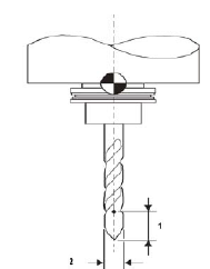
The figure below illustrates the tool length and diameter tolerances:
|
|
|
1. Length Tolerance |
|
|
2. Diameter Tolerance |
|
|
|
|
|
|
|
|
|
The software monitors the tool and determines if the tool is within the Length Tolerance or the Diameter Tolerance, or both if monitoring both length and diameter.
-
If the tool is shorter than the Length Tolerance value minus the length, the tool is worn.
-
If the tool’s diameter is less than the Diameter minus the programmed tolerance, the tool is worn.
-
If the tool is worn, the software checks for a sister tool.
-
If a Sister (spare) Tool has been entered in Tool Setup for this tool, axis motion stops and a tool change automatically occurs.
-
If there is no Sister Tool programmed for this tool, or if there is no ATC, axis motion will stop and a message appears telling you to change tools.
Refer to the Field Glossary for definitions of the Tool Quality Monitoring fields:
|
|
||
|
|
Automatic Tool Monitoring Parameter
Another method of monitoring tool quality is the Probing Parameter’s Automatic Tool Monitoring field. This setup automatically checks every probed tool for wear before and/or after cutting.
To set this parameter to automatically monitor tool quality:
-
From the Input screen, select the Program Parameters softkey.
-
Select the Probing tab.
-
Select the Automatic Tool Monitoring parameter:
-
Incoming Tool—tool is checked after it is inserted into spindle
-
Outgoing Tool—tool is checked before it is removed from the spindle
-
Both—checked before and after cut
-
-
Specify the Length Tolerance. This is the amount of deviation from the tool length programmed in Tool Setup screen.
-
Specify the Diameter Tolerance. This is the amount of deviation from the tool diameter programmed in Tool Setup screen.
The software monitors the tool and determines if the tool is within the Length Tolerance or the Diameter Tolerance, or both if monitoring both length and diameter.
-
If the tool is shorter than the Length Tolerance value minus the length, the tool is worn.
-
If the tool’s diameter is less than the Diameter minus the programmed tolerance, the tool is worn.
-
If the tool is worn, the software checks for a sister tool.
-
If a Sister (spare) Tool has been entered in Tool Setup for this tool, axis motion stops and a tool change automatically occurs.
-
If there is no Sister Tool programmed for this tool, or if there is no ATC, axis motion will stop and a message appears telling you to change tools.