Part Probe Calibration and Cycles
This section describes the probe calibration and cycles available with the Probing Option. Once the probing equipment is calibrated, the tool and part can be calibrated using the probing equipment. This information can be stored as appropriate in Tool or Part Setup, or in a data block to be executed with the part program.
Probe calibration is only required on systems that also have a tool probe installed. Calibration methods vary between systems with tool probing only, versus systems with both tool and part probing. See Probe Calibration—Absolute Tool Length mode or Probe Calibration—Zero Calibration mode of Tool Probing for details.
Part Probe Deflection Offset Calibration
Part probe deflection offsets are the difference between the contact point of the probe and the actual receipt of a probe deflection signal. The offsets may vary for each direction of deflection.
These offsets need to be adjusted during an initial probe installation, a new stylus installation, or for centering or re-centering a stylus. They do not need to be performed each time the control is reset.
Access the Part Probe Deflection Offset screen from the Part Setup screen. Select the Part Probing softkey followed by the Part Probe Deflection Offsets softkey. This screen appears with softkeys for selecting the method to use for determining offsets.
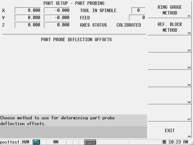
The sections that follow describe the procedures to follow for each method: Ring Gauge and Reference Block.
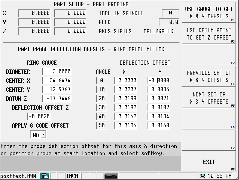
Ring Gauge
The Ring Gauge method probes in a circular pattern. Select the PART PROBE DEFLECTION OFFSETS softkey followed by the RING GAUGE softkey, and this screen appears:
Follow these steps to determine a Ring Gauge Deflection Offset:
-
Enter the Diameter of the part.
-
Use an indicator or some similar method to determine the center of the gauge. Enter the Center of the gauge in the Center X and Center Y fields.
-
Jog the spindle to a point in Z where the probe just touches the part and enter the value in the Datum Z field. This value can be entered manually or by pressing the Store Position key.
-
Position the probe tip inside the gauge at the desired depth and select the Use Gauge To Get X&Y Offsets softkey. The Start button begins to flash.
-
Press the Start button to begin the cycle.
-
The probe touches the part at 36 points (10° increments) inside the gauge to automatically calculate the X and Y offsets. To determine the Z offset, position the probe tip above the chosen datum point and select the Use Datum Point To Get Z Offset softkey. The Start button begins to flash.
-
Press the Start button to begin the cycle.
-
The probe touches off the datum point and calculates the offset.
-
The Offset values appear on the screen and are stored in memory.
This offset will be used anytime the control uses a probe location.
Offset values may be entered manually by the operator. If you know the readings are off by a certain amount, you can make adjustments without even using the probe.
The sign of the offset should be + for plus axis deflections and - for minus axis deflections.
|
|
The Apply G Code Offset parameter applies the deflection offsets to G31 commands when conversational and NC probing are used together. |
Reference Block
The Reference Block method probes in the + or - X or Y direction. Select the Part Probe Deflection Offsets softkey followed by the Reference Block Method softkey, and this screen appears:
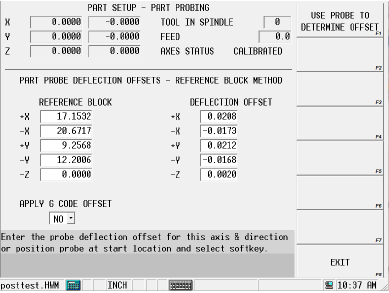
Follow these steps to determine the Reference Block Deflection Offsets for the X or Y axes:
-
Enter X or Y values manually in the Reference Block X or Y fields.
-
Position the cursor under the Deflection Offset column at the offset to be determined.
-
Manually jog the machine so the part probe is in the proper location to touch off the reference block for the desired axis and direction.
-
Select the Use Probe To Determine Offset softkey, and the Start button begins to flash.
-
Press the Start Button to start the cycle. The probe touches off the reference block. The offset values are calculated, appear on the screen, and are stored in memory.
This offset is used when the control uses a probe location.
Follow these steps to determine the offset for the Z axis:
-
Jog the probe to the top of the reference block.
-
Use a feeler gauge to determine where the tip of the stylus would touch the reference block. Enter this value in the -Z field in the Reference Block column.
-
Select the Use Probe To Determine Offset softkey. The probe touches off the part in the Z axis to determine the offset.
Offset values may be entered manually by the operator. If you know the readings are off by a certain amount, you can make adjustments without using the probe.
The sign of the offset should be + for plus axis deflections and - for minus axis deflections.
|
|
The Ring Gauge method is more accurate than the Reference Block method. |
-
The probe measures the part at 36 points in 10° increments on the ring gauge.
-
The 4 points measured on the reference block correspond to the 0°, 90°, 180°, and 270° values on the ring gauge. The remaining 32 values are estimated using the 4 actual measurements to fill in the 10° incremental offsets.
|
|
The Apply G Code Offset parameter applies the deflection offsets to G31 commands when conversational and NC probing are used together. |
Conversational Part Probing Cycles
Part probing is used for locating the position and alignment of the part on the table. Inserting a Probe Part Setup data block to run from the part program allows you to probe multiple parts and locate them at run time. This section describes probing cycles which are used for creating Probe Part Setup data blocks.
The software uses information programmed in the Part Setup screen to perform the Probing Cycles in Manual or Automatic mode.
There are two types of cycles available for probing different types of part features: Part Setup Probing Cycles and Part Skew Probing Cycles.
To select the Part Probe cycle type:
-
Select the Input console key to access the Input screen.
-
Press the Part Setup softkey.
-
Press the Part Probing softkey. The Part Setup screen is displayed with the Part Probing menu.
-
Select the Part Zero Probe Cycles softkey for the Part Setup Probing Cycles. Refer to Part Setup Probing Cycles for details about programming these Manual Mode cycles. Refer to Automatic Mode for information about programming these Auto Mode cycles.
-
Select the Part Skew Probe Cycles softkey to access the Part Skew Probing Cycles. Refer to Part Skew Probing Cycles for details about programming these Manual Mode cycles.Refer to Automatic Mode for information about programming these Auto Mode cycles.
-
Select the probing cycle type from the Part Setup screen with the Part Probing softkey.The cycles provide a method for allowing the software to automatically enter the Part Zero X, Part Zero Y, Probe Z, and X/Y Skew (deg) fields in the Part Setup screen.
Part Setup Screen
In addition to the standard Part Setup fields defined in the Getting Started with WinMax Mill manual, the software updates these Part Setup fields with data obtained during the probing cycles:
Refer to Determine Probe Z of Tool Probing for more details about Probe Z calculations.
Part probing may be run either from Manual Mode or from Auto Mode inside the part program. The sections that follow describe the different types of Manual Mode Probing Cycles. Auto Mode probing is described at the end of this chapter.
Part Probe Deflection
During the probing cycles described in this section, the part probe positions and moves at Approach Feed until it reaches the geometry. Then it backs up and moves again at Measurement Feed until it deflects the geometry a second time. The Measurement Feed touches are repeated a total of Repetitions times and the average is used.
Part Probe Working Envelope
The part probe cycles allow the part probe to operate within the constraints set in the Part Setup—Part Probe Parameters. A working envelope containing safe part probe travel limits is stored in the Part Probing Parameters.
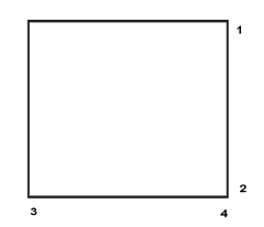
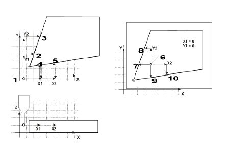
The working envelope represents the area on the machine table in which the probe can search for geometric features. The travel limits mentioned in each of the Manual Mode Part Setup Probing Cycles and the Manual Mode Part Skew Probing Cycles are set in the working envelope. This area is determined by these fields in the Part Probing Parameters screen: X Min, X Max, Y Min, Y Max, and Z Min. Z Min is a location above the table. The X and Y parameters are illustrated in the figure below:
|
|
|
1. Y Max |
|
|
2. Y min |
|
|
3. X Min |
|
|
4. X Max |
|
|
|
|
|
If the probe reaches any part probe travel limit before reaching the part feature, a fault occurs, motion stops, and an error message appears on the screen. |
Each cycle’s feed rate is determined by the value set in the Part Probing Parameters Approach Feed and Measurement Feed fields.
Part Setup Probing Cycles
The table below describes the process for each Part Setup Probing Cycle:
|
Cycle Type |
Parameter Input |
Automatic Execution |
Results Displayed |
Optional Storage |
|---|---|---|---|---|
|
Edge |
Axis Probe Direction Positive OR Negative Preset X or Y |
Approach edge. Retract. Return to Start Position. |
Deflection Position X, Y, or Z |
Deflection Position OR Probe Z. |
|
Hole Circle |
Start Angle 1, 2, 3 Preset X Preset Y |
Approach 3 Circle Points from inside. Position Probe into Center. |
Center X Center Y Diameter |
Center is Part Zero X and |
|
Cylinder |
Probing Radius Start Angle 1, 2, 3 Z Depth Preset X Preset Y |
Approach 3 Cylinder points from outside. Position Probe above cylinder Center. |
Center X Center Y Diameter |
Center is Part Zero X and |
|
Rectangular Pocket |
Preset X Preset Y |
Approach the 4 pocket walls from inside. Position Probe into pocket Center. |
Center (X) Center (Y) Length (X) Length (Y) |
Center is Part Zero X and |
|
Rectangular Solid
|
Probing Length (X) Probing Length (Y) Z Depth Preset X Preset Y |
Approach the 4 Rectangle walls from outside. Position Probe above rectangle Center. |
Center (X) Center (Y) Length (X) Length (Y)
|
Center is Part Zero X and |
|
Cycle Type |
Parameter Input |
Automatic Execution |
Results Displayed |
Optional Storage |
|---|---|---|---|---|
|
Plane Intersection |
X Probe Direction Offset 1 Offset 2 Y Probe Direction Offset 1 Offset 2 Preset X Preset Y |
Approach 2 points on each of the two planes. Return to Start Position. |
Intersection point of the two planes in the |
Intersection point is |
|
Slot Inside |
Preset X OR Preset Y |
Approach the 2 slot walls from inside. Position Probe into slot Center. |
Center (X) OR Center (Y) Length (X) OR Length (Y)
|
Center is Part Zero X OR
|
|
Web Outside |
Probing Length (X) OR Probing Length (Y) Z Depth Preset X OR Preset Y |
Approach the 2 web walls from outside. Position Probe above web Center. |
Center (X) OR Center (Y) Length (X) OR Length (Y)
|
Center is Part Zero X OR
|
Manual Mode Part Setup Probing Cycles
During a Part Setup Probing cycle, the probe moves to specified points on the part, deflects, and stops in the center or at the Start Position, depending on the part feature. From the Part Setup screen, use the PROBING (F5) softkey to access the Probing Cycles.
Each cycle is described in detail in the following sections. When the cycle is finished, the software displays values representing the desired features. The fields for each cycle vary and are defined with each cycle description.
You can accept these values by pressing the ACCEPT POSITION AS PART ZERO softkey when it appears. If you have entered Preset X or Preset Y offsets, these offsets are subtracted from the probed Part Zero values, and the new Part Zero values appear after pressing the ACCEPT POSITION AS PART ZERO softkey.
Follow these steps to access the Part Probe Cycles:
-
From the Part Setup screen, select the Part Probing softkey.
-
Select the Part Zero Probe Cycles softkey. The probe cycle softkeys appear. Select a softkey to select a cycle.
Depending on the Probing Cycle selected, different probing fields appear on the Part Setup screen.
|
|
The following sections describe how to program each of the Part Setup Probing Cycles. |
Edge
An Edge Cycle is used for determining the location of a specified edge of the part. During an Edge Cycle, the part probe moves to the X, Y, or Z edge of the part and records the deflection position.
The figure below shows part probe movement during X, Y, and Z Edge Cycles:
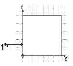
Edge Probing in X direction (positive) Top View 1 Start Position |
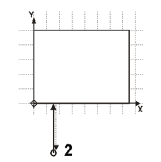
Edge Probing in Y direction (positive) Top View 2 Start Position |
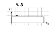
Edge Probing in Z direction Side View 3 Start Position |
The figure below shows a side view of an Edge cycle probing in the X direction:
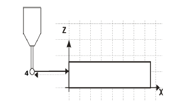
Edge Probing in X direction (positive) Side View 4 Start Position |
In addition to the standard Part Setup fields which are defined in the Getting Started with WinMax Mill manual, these Part Setup fields appear for the Edge Probing Cycle:
Follow these steps to program an Edge Probing Cycle:
-
From the Part Zero Probe Cycles softkey menu, select Edge.
-
In the Probing Axis field, select the axis to move toward the edge of the part: X Axis, Y Axis, or Z Axis.
-
In the Probing Direction field, select the direction to probe: Positive or Negative. This field appears when the Probing Axis is X or Y. It is not available for Z Probing Axis.
-
If you want to program an offset from Part Zero X or Part Zero Y, enter the offset value in the Preset X or Preset Y field. This field appears when the Probing Axis is X or Y. It is not available for Z Probing Axis.
When the Part Setup fields have been entered, start the Edge Probing Cycle:
-
Place the part probe in the spindle and jog the probe to the Start Position, near the edge to be probed.
-
Press the Start Probing Cycle softkey. The Start Cycle button flashes.
-
Press the flashing Start Cycle button.
-
The probing axis moves in the specified direction until the probe is deflected.
-
If no deflection occurs before the probe reaches the probe’s travel limit, the cycle is stopped and an error message appears.
-
To clear the error message and return to the Part Setup screen, press any key.
-
Check the Part Probe Parameters and the part fixturing. Make adjustments as necessary and re-start the cycle.
-
-
The deflection position appears in the Edge (X,Y, or Z) field when the cycle is finished.
-
The probing axis returns to the Start Position.
-
-
The Accept Position As Part Zero and Do Not Accept softkeys appear. Press the appropriate softkey.
-
The Accept Position As Part Zero softkey accepts the edge position and subtracts the Preset X or Y value to determine Part Zero.
-
The Do Not Accept softkey ignores the edge position value and the Preset X or Y value. Part Zero remains unchanged.
-
-
The initial Part Setup screen appears with Part Zero entries established during the cycle.
Hole or Circle Pocket
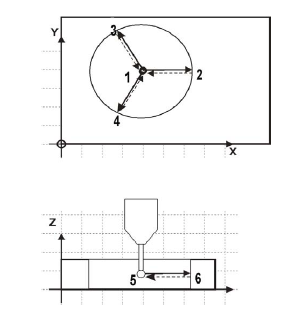
The Hole or Circle Pocket Cycle is used for determining the center location and the diameter of a hole or pocket. During a Hole or Circle Pocket Cycle, the part probe moves from the inside of the circle out to three points on the edge, touches at each point, and returns to the Start Position within the circle after each touch. The software records each deflection position and calculates the center location. The probe positions in the center of the pocket.
The figure below shows part probe movement during a Hole or Circle Pocket Cycle:
|
1. Start Position |
|
2. Start Angle 1 |
|
|
3. Start Angle 2 |
|
|
4. Start Angle 3 |
|
|
5. Start Position |
|
|
6. Start Angle 1 |
In addition to the standard Part Setup fields which are defined in the Getting Started with WinMax Mill manual, these Part Setup fields appear for the Hole or Circle Pocket Probing Cycle:
Follow these steps to program a Hole or Circle Pocket Probing Cycle:
-
From the Part Zero Probe Cycles softkey menu, select Hole or Circle Pocket.
-
In the Start Angle fields, enter the desired approach angles.
-
If you want to program an offset from Part Zero X or Part Zero Y, enter the offset value in the Preset X or Preset Y field.
When the Part Setup fields have been entered, start the Hole or Circle Pocket Probing Cycle:
-
Place the part probe in the spindle and jog the probe to the Start Position, into the pocket and below the surface.
-
Press the START PROBING CYCLE (F1) softkey. The Start Cycle button flashes.
-
Press the Start Cycle button.
-
The probe moves along Start Angle 1 until it is deflected at the edge of the hole or circle pocket.
-
If no deflection occurs before the probe reaches its travel limit, the cycle is stopped and an error message appears.
-
To clear the error message and return to the Part Setup screen, press any key.
-
Check the Part Probe Parameters and the part fixturing. Make adjustments as necessary and re-start the cycle.
-
-
After the first deflection, the probe returns to the Start Position.
-
The probe moves along Start Angle 2 to a second contact point.
-
After the deflection, the probe returns to the Start Position.
-
The probe moves along Start Angle 3 to a third contact point.
-
After the deflection, the probe returns to the Start Position.
-
Using the three contact points, the control calculates the diameter and the center (X and Y) of the hole.
-
The probe moves to the center of the hole or circle pocket. The results appear in the Center X, Center Y, and Diameter fields.
-
-
The ACCEPT POSITION AS PART ZERO (F1) and DO NOT ACCEPT (F2) softkeys appear. Press the appropriate softkey.
-
The ACCEPT POSITION AS PART ZERO (F1) softkey accepts the center position and subtracts the presets to determine Part Zero.
-
The DO NOT ACCEPT (F2) softkey ignores the center value and the Preset X or Y value. Part Zero remains unchanged.
-
-
The initial Part Setup screen appears with Part Zero entries established during the cycle.
Cylinder
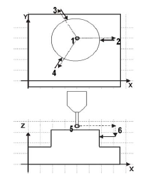
The Cylinder Cycle is used for determining the center location and the diameter of a cylinder. During a Cylinder Cycle, the part probe moves from the Start Position above the cylinder, out and down to three points around the diameter. The probe touches at each point and returns up and over to the Start Position above the cylinder after each touch. The software determines the diameter and the center location.
The figure below shows part probe movement during a Cylinder Cycle:
|
1. Start Position |
|
2. Start Angle 1 |
|
|
3. Start Angle 2 |
|
|
4. Start Angle 3 |
|
|
5. Start Position |
|
|
6. Start Angle 1 |
In addition to the standard Part Setup fields which are defined in the Getting Started with WinMax Mill manual, these Part Setup fields appear for the Cylinder Cycle:
Follow these steps to program a Cylinder Probing Cycle:
-
From the Part Zero Probe Cycles softkey menu, select Cylinder.
-
In the Probing Radius field, enter the probe search radius.
-
In the Start Angle fields, enter the desired approach angles.
-
In the Z Depth field, enter the distance the Z axis moves down before changing direction and searching horizontally for each contact point.
-
If you want to program an offset from Part Zero X and Part Zero Y, enter the offset value in the Preset X and Preset Y field.
When the Part Setup fields have been entered, start the Cylinder Probing Cycle:
-
Place the part probe in the spindle and jog the probe to the Start Position, above the cylinder.
-
Press the START PROBING CYCLE (F1) softkey. The Start Cycle button flashes.
-
Press the flashing Start Cycle button.
-
The probe moves along Start Angle 1 until it reaches the Probing Radius.
-
If no deflection occurs before the probe reaches the probe’s travel limit, the cycle is stopped and an error message appears.
-
To clear the error message and return to the Part Setup screen, press any key.
-
Check the Part Probe Parameters and the part fixturing. Make adjustments as necessary and re-start the cycle.
-
-
The probe moves down until it reaches Z Depth.
-
If deflection occurs during the Z move, axis motion stops and an error message appears.
-
To clear the error message and return to the Part Setup screen, press any key.
-
Check the Part Probe Parameters and the part fixturing. Make adjustments as necessary and re-start the cycle.
-
-
The probe moves backwards in the X/Y plane toward the Start Position in order to find a contact point.
-
After deflection, the probe moves up and over to the Start Position above the cylinder.
-
The probe moves along Start Angle 2 until it reaches the Probing Radius. The same motion occurs as with Start Angle 1.
-
After the deflection, the probe moves up and over to the Start Position above the cylinder.
-
The probe moves along Start Angle 3 until it reaches the Probing Radius. The same motion occurs as with Start Angles 1 and 2.
-
After the third deflection, the control uses the three contact points and calculates the diameter and center (X and Y) of the cylinder.
-
The probe moves up and over to the center above the Z Plane of the cylinder. The results appear in the Center X, Center Y, and Diameter fields.
-
-
The ACCEPT POSITION AS PART ZERO (F1) and DO NOT ACCEPT (F2) softkeys appear. Press the appropriate softkey.
-
The ACCEPT POSITION AS PART ZERO (F1) softkey accepts the center and subtracts the presets to determine part zero.
-
The DO NOT ACCEPT (F2) softkey ignores the center values and the Preset X or Y value. Part Zero remains unchanged.
-
-
The initial Part Setup screen appears with Part Zero entries established during the cycle.
Rectangular Pocket Inside
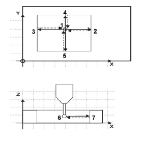
The Rectangular Pocket Inside (or Rectangular Pocket) Cycle is used for determining the center location of the pocket and the X and Y length of the rectangle. During a Rectangular Pocket Cycle, the part probe moves from inside the pocket out to a point on each edge of the rectangle, touches at each point, and returns to the Start Position after each touch. The software records each deflection position and calculates the center location and lengths.
The figure below shows part probe movement during a Rectangular Pocket Cycle.
|
|
|
1. Start Position |
|
|
2. Point 1 |
|
|
3. Point 2 |
|
|
4. Point 3 |
|
|
5. Point 4 |
|
|
6. Start Position |
|
|
7. Point 1 |
In addition to the standard Part Setup fields which are defined in the Programming Basics chapter of the Getting Started with WinMax manual, these Part Setup fields appear for the Rectangular Pocket Cycle:
The offset(s) will be subtracted from the center point of the pocket and applied to Part Zero X and Y if you select the ACCEPT POSITION AS PART ZERO softkey, which appears after the cycle has been run.
Follow these steps to program a Rectangular Pocket Cycle:
-
From the Part Zero Probe Cycles softkey menu, select Rectangular Pocket Inside.
-
If you want to program an offset for Part Zero X or Part Zero Y, enter the offset value in the Preset X or Preset Y field.
When the Part Setup fields have been entered, start the Rectangular Pocket Cycle:
-
Place the part probe in the spindle and jog the probe to the Start Position, into the pocket and below the surface.
-
Press the START PROBING CYCLE softkey. The Start Cycle button flashes.
-
Press the Start Cycle button.
-
The probe moves in the positive X direction until it is deflected at the edge of the pocket.
-
If no deflection occurs before the probe reaches its horizontal travel limit, the cycle is stopped and an error message appears.
-
To clear the error message and return to the Part Setup screen, press any key.
-
Check the Part Probe Parameters and the part fixturing. Make adjustments as necessary and re-start the cycle.
-
-
After the first deflection, the probe returns to the Start Position.
-
The probe moves in the negative X direction, reaches a second contact point, and returns to the Start Position.
-
The probe moves in the positive Y direction, reaches a third contact point, and returns to the Start Position.
-
The probe moves in the negative Y direction, reaches a fourth contact point, and returns to the Start Position.
-
Using the four contact points, the control calculates the length of the pocket in the X and Y directions and the center (X and Y) of the pocket.
-
The probe moves to the center of the rectangle. The results are displayed on the screen in the Center X, Center Y, Length (X), and Length (Y) fields.
-
-
The ACCEPT POSITION AS PART ZERO and DO NOT ACCEPT softkeys appear. Press the appropriate softkey.
-
The ACCEPT POSITOIN AS PART ZERO softkey accepts the center and subtracts the presets to determine part zero.
-
The DO NOT ACCEPT softkey ignores the center and length values and the Preset X or Y value. Part Zero remains unchanged.
-
-
The initial Part Setup screen appears with Part Zero entries established during the cycle.
Rectangular Solid Outside
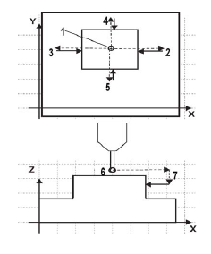
A Rectangular Solid Outside (or Rectangular Solid) Cycle is used for determining the center location of the pocket and the X and Y length of the rectangle. During a Rectangular Solid Cycle, the part probe moves from above the rectangle out and down to a point on each of the four walls, touches at each point, and returns to the Start Position after each touch. The software records each deflection position and calculates the center position and lengths.
The figure below shows part probe movement during a Rectangular Solid Cycle:
|
|
|
1. Start Position |
|
|
2. Point 1 |
|
|
3. Point 2 |
|
|
4. Point 3 |
|
|
5. Point 4 |
|
|
6. Start Position |
|
|
7. Point 1 |
In addition to the standard Part Setup fields which are defined in the Programming Basics chapter of the Getting Started with WinMax manual, these Part Setup fields appear for the Rectangular Solid Cycle:
|
|
||
|
|
||
|
|
||
|
|
||
|
|
Follow these steps to program a Rectangular Solid Cycle:
-
From the Part Setup Probe Cycles softkey menu, select Rectangular Solid Outside.
-
In the Probing Length X field, enter an estimate for the X length.
-
In the Probing Length Y field, enter an estimate for the Y length.
-
In the Z Depth field, enter the distance the Z axis should move down.
-
If you want to program an offset for Part Zero X and Part Zero Y, enter the offset value in the Preset X and Preset Y field.
When the Part Setup fields have been entered, start the Rectangular Solid Cycle:
-
Place the part probe in the spindle and jog the probe to the Start Position, above the middle of the rectangle.
-
Press the START PROBING CYCLE (F1) softkey. The Start Cycle button flashes.
-
Press the Start Cycle button.
-
The probe moves in the positive X direction, until it reaches its horizontal travel limit determined by the Probing Length X field.
-
If no deflection occurs before the probe reaches the probe’s travel limit, the cycle is stopped and an error message appears.
-
To clear the error message and return to the Part Setup screen, press any key.
-
Check the Part Probe Parameters and the part fixturing. Make adjustments as necessary and re-start the cycle.
-
-
The probe moves down until it reaches Z Depth.
-
If deflection occurs during the Z move, axis motion stops and an error message appears.
-
To clear the error message and return to the Part Setup screen, press any key.
-
Check the Part Probe Parameters and the part fixturing. Make adjustments as necessary and re-start the cycle.
-
-
The probe moves backwards in the X/Y plane toward the Start Position and deflects.
-
The probe returns up and over to the Start Position.
-
The probe moves in the negative X direction until it reaches its horizontal travel limit determined by the Probing Length X field.
-
The probe moves down until it reaches Z Depth.
-
The probe moves backwards in the X/Y plane toward the Start Position and deflects.
-
The probe moves up and over to the Start Position.
-
The probe moves in the positive Y direction until it reaches its horizontal travel limit determined by the Probing Length Y field.
-
The probe moves down until it reaches Z Depth.
-
The probe moves backwards in the X/Y plane toward the Start Position and deflects.
-
The probe moves up and over to the Start Position.
-
The probe moves in the negative Y direction until it reaches its horizontal travel limit determined by the Probing Length Y field.
-
The probe moves down until it reaches Z Depth.
-
The probe moves backwards in the X/Y plane toward the Start Position and deflects.
-
The probe moves up and over to the Start Position.
-
After the last deflection, the control calculates the X and Y lengths of the solid and the center (X and Y) of the rectangle.
-
The results appear in the Center X, Center Y, Length (X), and Length (Y), fields. The probe moves to the center above the rectangle.
-
-
The ACCEPT POSITION AS PART ZERO (F1) and DO NOT ACCEPT (F2) softkeys appear. Press the appropriate softkey.
-
The ACCEPT POSITION AS PART ZERO (F1) softkey accepts the center and subtracts the presets to determine part zero.
-
The DO NOT ACCEPT (F2) softkey ignores the center and length values and the Preset X or Y value. Part Zero remains unchanged.
-
-
The initial Part Setup screen appears with Part Zero entries established during the cycle.
Plane Intersection (Non-Rectangular Corner)
A Plane Intersection Cycle is used for determining an X and Y intersection for a non-rectangular corner. During a Plane Intersection Cycle, the part probe moves from an offset position to two points in the X direction and two points in the Y direction to determine an X and Y intersection point.
The Plane Intersection cycle can be used with solid or pocket geometry. The figure below shows part probe movement with the two types of geometry:
|
1. Solid geometry Start |
|
2. Solid Geometry Point 1 |
|
|
3. Solid Geometry Point 2 |
|
|
4. Solid Geometry Point 3 |
|
|
5. Solid Geometry Point 4 |
|
|
6. Pocket Geom. Start |
|
|
7. Pocket Geom. Point 1 |
|
|
8. Pocket Geom. Point 2 |
|
|
9. Pocket Geom. Point 3 |
|
|
10. Pocket Geom. Point 4 |
In addition to the standard Part Setup fields which are defined in the Programming Basics chapter of the Getting Started with WinMax manual, these Part Setup fields appear for the Plane Intersection Cycle:
Follow these steps to program a Plane Intersection Cycle:
-
From the Part Zero Probe Cycles softkey menu, select Plane Intersection.
-
In the Probing Direction X field, select Positive or Negative.
-
In the Offset 1 field, enter the position for the first Y Offset, relative to the Start Position.
-
In the Offset 2 field, enter the position for the second Y Offset, relative to the Start Position.
-
In the Probing Direction Y field, select Positive or Negative.
-
In the Offset 1 field, enter the position for the first X Offset, relative to the Start Position.
-
In the Offset 2 field, enter the position for the second X Offset, relative to the Start Position.
-
If you want to program an offset from Part Zero X or Part Zero Y, enter the offset value in the Preset X or Preset Y field.
When the Part Setup fields have been entered, start the Plane Intersection Cycle:
-
Place the part probe in the spindle and jog the probe into the Start Position, near the non-rectangular corner.
-
Press the START PROBING CYCLE (F1) softkey. The Start Cycle button flashes.
-
Press the flashing Start Cycle button.
-
The probe moves the direction specified in Probing Direction X the distance specified in Offset 1.
-
If no deflection occurs before the probe reaches the probe’s travel limit, the cycle is stopped and an error message appears.
-
To clear the error message and return to the Part Setup screen, press any key.
-
Check the Part Probe Parameters and the part fixturing. Make adjustments as necessary and re-start the cycle.
-
-
The probe reaches the first contact point with the first edge in the X direction, deflects, and moves to the position specified in Offset 2.
-
The probe reaches the second contact point in the X direction and deflects.
-
The probe returns to the starting point.
-
The probe moves the direction specified in Probing Direction Y the distance specified in Offset 1.
-
The probe reaches the first contact point with the first edge in the Y direction, deflects, and moves to the position specified in Offset 2.
-
The probe reaches the second contact point in the Y direction and deflects.
-
The probe returns to the Start Position.
-
Using the four contact points, the control calculates the X and Y intersection points. The results appear in the Corner X and Corner Y fields.
-
-
The ACCEPT POSITION AS PART ZERO (and DO NOT ACCEPT softkeys appear. Press the appropriate softkey.
-
The ACCEPT POSITION AS PART ZERO (F1) softkey accepts the corner position and subtracts the Preset X or Y value to determine Part Zero.
-
The DO NOT ACCEPT (F2) softkey ignores the corner values and the Preset X or Y value. Part Zero remains unchanged.
-
-
The initial Part Setup screen appears with Part Zero entries established during the cycle.
Part Zero Storage
At the end of each Probing Cycle, the results of the cycle are displayed on the screen. These results are displayed in machine coordinates and do not include the Preset values.
|
Cycle |
Results |
|---|---|
|
Edge |
Contact Position (X, Y, or Z) |
|
Hole or Circle Pocket |
Diameter, Center (X and Y) |
|
Cylinder |
Diameter, Center (X and Y) |
|
Rectangular Pocket |
Lengths (X and Y), Center (X and Y) |
|
Rectangular Solid |
Lengths (X and Y), Center (X and Y) |
|
Plane Intersect |
Corner (X and Y) |
Selecting the ACCEPT POSITION AS PART ZERO softkey accepts the probed values and subtracts the presets to determine part zero. The new Part Zero values appear in the Part Zero X and Part Zero Y fields.
With an Edge probing cycle the probe moves only one axis. Therefore, only one of Part Zero X, Part Zero Y, or Probe Z is set. With all other cycles, both Part Zero X and Part Zero Y are determined at the same time.
Part Skew Probing Cycles
The following table describes the process of the Skew Probing Cycles:
|
Skew Cycle Type |
Cycle Parameter Input |
Automatic Execution |
Display of the results |
Optional storage |
|---|---|---|---|---|
|
Edge |
Axis X, Y, or Z Probe Direction: Preset X or |
Cycle Start Approach edge. Retract. Return to Start Position. |
Deflection Position X, Y, or Z Skew Angle (deg) |
Skew Angle |
|
Hole or Circle |
Start Angle 1, 2, 3 Preset X Preset Y |
Cycle Start Approach 3 Circle Points from inside. Position Probe into Center. |
Center X Center Y Diameter Skew Angle (deg) |
Skew Angle |
|
Cylinder |
Probing Radius Z Depth Start Angle 1, 2, 3 Preset X Preset Y |
Cycle Start Approach 3 Cylinder Points from outside. Position Probe above cylinder Center. |
Center X Center Y Diameter Skew Angle (deg) |
Skew Angle |
|
Rectangular Pocket |
Preset X Preset Y |
Cycle Start Approach the 4 pocket walls from inside. Position Probe into pocket Center. |
Center X Center Y Length X Length Y Skew Angle (deg) |
Skew Angle |
|
Rectangular Solid |
Probing Length X Probing Length Y Z Depth Preset X Preset Y |
Cycle Start Approach the 4 Rectangle walls from outside. Position Probe above rectangle Center. |
Center X Center Y Length X Length Y Skew Angle (deg) |
Skew Angle |
|
Two Point Edge |
Axis X or Y Probe Direction: Offset |
Cycle Start Approach two points on the edge. Return to Start Position. |
Skew Angle (deg) |
Skew Angle |
Manual Mode Part Skew Probing Cycles
From the Part Setup screen, use the PROBING softkey to access the Probing Cycles. During a Part Skew Probing cycle the probe moves to specified points on the part, deflects, and stops in the center of the part feature. These cycles detect and compensate for X/Y skew in the workpiece. X/Y skew represents, in degrees, how far the part is from perfect alignment with the table. C axis skew may be stored in Part Zero C instead of X/Y Skew on machines with a C axis.
-
A positive skew angle means the part is rotated in a counterclockwise direction from the machine axes (as viewed from above the part).
-
A negative skew angle indicates a clockwise rotation from the machine axes.
Although this angle, if known, may be manually typed in using the keypad, it is easier and more accurate to let the probe find the skew angle and automatically enter it.
|
|
For best results, it is recommended that you use the probe for determining Part Zero X, Part Zero Y, Part Zero C and X/Y Skew. Entering values for any of these fields with the keypad reduces the amount of information available for skew calculations. Also, the software must make assumptions that may reduce accuracy. |
After probing the Part Zero position as a reference, the skew cycles allow you to probe a second feature on the part and adjust all machining operations by the skew angle to exactly match the part.
When the cycle is finished, the software displays values representing the desired features. The fields for each cycle vary and are defined with each cycle description.
You can accept these values by pressing the appropriate Accept Skew Angle? softkey when it appears. Preset X or Preset Y offsets are used in the skew calculation. The presets are subtracted from the probed Part Zero values, and the new Part Zero values appear after pressing the STORE AS X/Y SKEW or STORE AS PART ZERO C softkey.
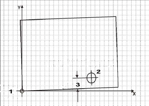
The figure below illustrates a skewed workpiece with a Preset Y offset.
|
|
|
|
|
|
|
|
|
1. Part Zero (Corner, first reference) |
|
|
2. Hole Centerpoint (used as a second reference for skew compensation) |
|
|
3. Preset Y |
|
|
|
|
|
|
|
|
|
|
|
Enter offsets for Preset X and Preset Y for a precise Skew Angle. If only one Preset value is entered, the skew angle will be approximate and should not exceed 3 degrees. Skew Compensation is intended to be used for correcting a slight misalignment. If the skew angle contains only one Preset value and is greater than approximately 3 degrees, then Part Skew probing may not be exact, especially for Edge and Rectangular cycles. |
Follow these steps to perform a Skew Probe Cycle for workpiece skew compensation:
-
Perform the Part Zero Probe Cycle. Refer to the appropriate Part Probe Cycle in this chapter (i.e., Edge, Cylinder, etc.) or more information.
-
From the Part Setup screen, select the PROBING softkey followed by the PART SKEW PROBE CYCLES softkey to access the Part Skew Probe Cycles.
-
The Skew Probe Cycle Type softkeys appear. Select the appropriate softkey for the desired cycle.
Depending on the Skew Probing Cycle selected, different probing fields appear on the Part Setup screen.
|
|
The following sections describe how to program each of the Part Skew Probing Cycles. |
Edge Skew
Follow these steps to program an Edge Skew Probing Cycle:
-
From the Part Setup Skew Probe Cycle softkey menu, select Edge.
-
In the Probing Axis field, select the axis to move toward the edge of the part: X Axis, Y Axis, or Z Axis.
-
In the Probing Direction field, select the direction to probe: Positive or Negative. Z Axis always probes in the Negative direction.
-
Program an offset in the Preset X or Preset Y field, if desired.
When the Part Setup fields have been entered, start the Edge Skew Probing Cycle:
-
Place the part probe in the spindle and jog the probe to the Start Position, near the edge to be probed.
-
Press the START PROBING CYCLE (F1) softkey. The Start Cycle button flashes.
-
Press the Start Cycle button.
The tool motion for an Edge Skew Cycle is the same as the motion described for an Edge Cycle. The results appear in the Edge (X,Y, or Z) and Skew Angle (Deg) fields. The probe returns to the Start Position.
-
The ACCEPT X/Y SKEW ANGLE (F1) and DO NOT ACCEPT (F2) softkeys appear.
-
The ACCEPT X/Y SKEW ANGLE (F1) softkey accepts the skew position and subtracts the Preset X or Y value to determine Part Zero.
-
The DO NOT ACCEPT (F2) softkey ignores the edge position value and the Preset X or Y value. Part Zero remains unchanged.
-
Refer to Part Zero Storage for more information.
-
The initial Part Setup screen appears with the skew value established during the cycle stored in the X/Y Skew (deg) field, if accepted.
Hole or Circle Pocket Skew
Follow these steps to program a Hole or Circle Pocket Skew Probing Cycle:
-
From the Part Setup Skew Probe Cycle softkey menu, select the HOLE OR CIRCLE POCKET (F2) softkey.
-
In the Start Angle 1, Start Angle 2, and Start Angle 3 fields, enter the desired approach angles.
-
Program an offset in the Preset X and/or Preset Y field(s), if desired.
When the Part Setup fields have been entered, start the Hole or Circle Skew Probing Cycle:
-
Place the part probe in the spindle and jog the probe to the Start Position, inside the pocket near the center.
-
Press the START PROBING CYCLE (F1) softkey. The Start Cycle button flashes.
-
Press the Start Cycle button.
The tool motion for a Hole or Circle Pocket Skew Probing Cycle is the same as the motion described for a Hole or Circle Pocket Cycle. The results appear in the Center X, Center Y, Diameter, and Skew Angle (deg) fields. The probe stops in the center of the pocket.
-
The ACCEPT X/Y SKEW ANGLE (F1) and DO NOT ACCEPT (F2) softkeys appear.
-
The ACCEPT X/Y SKEW ANGLE (F1) softkey accepts the skew position and subtracts the Preset X or Y value to determine Part Zero.
-
The DO NOT ACCEPT (F2) softkey ignores the edge position value and the Preset X or Y value. Part Zero remains unchanged.
-
Refer to Part Zero Storage for more information.
-
The initial Part Setup screen appears with the skew value established during the cycle stored in the X/Y Skew (deg) field, if accepted.
Cylinder Skew
Follow these steps to program a Cylinder Skew Probing Cycle:
-
From the Part Setup Skew Probe Cycle softkey menu, select Cylinder.
-
In the Probing Radius field, enter the probe search radius.
-
In the Start Angle fields, enter the desired approach angles.
-
In the Z Depth field, enter the distance the Z axis moves down before changing direction and searching horizontally for each contact point.
-
Program an offset in the Preset X and/or Preset Y field(s), if desired.
When the Part Setup fields have been entered, start the Cylinder Skew Probing Cycle:
-
Place the part probe in the spindle and jog the probe to the Start Position, above the cylinder near the center.
-
Press the START PROBING CYCLE (F1) softkey. The Start Cycle button flashes.
-
Press the Start Cycle button.
The tool motion for a Cylinder Skew Probing Cycle is the same as the motion described for a Cylinder Cycle. The results appear in the Center X, Center Y, Diameter, and Skew Angle (deg) fields. The probe stops in the center above the cylinder.
-
The ACCEPT X/Y SKEW ANGLE (F1) and DO NOT ACCEPT (F2) softkeys appear.
-
The ACCEPT X/Y SKEW ANGLE (F1) softkey accepts the skew position and subtracts the Preset X or Y value to determine Part Zero.
-
The DO NOT ACCEPT (F2) softkey ignores the edge position value and the Preset X or Y value. Part Zero remains unchanged.
-
Rectangular Pocket Skew
Follow these steps to program a Rectangular Pocket Skew Cycle:
-
From the Part Setup Skew Probe Cycle softkey menu, select Rectangular Pocket Inside.
-
Program an offset for the Preset X and/or Preset Y field, if desired.
When the Part Setup fields have been entered, start the Rectangular Pocket Skew Probing Cycle:
-
Place the part probe in the spindle and jog the probe to the Start Position, inside the rectangular pocket.
-
Press the START PROBING CYCLE (F1) softkey. The Start Cycle button flashes.
-
Press the Start Cycle button.
The tool motion for a Rectangular Pocket Skew Probing Cycle is the same as the motion described for a Rectangular Pocket Cycle. The results are displayed on the screen in the Center X, Center Y, Length (X), Length (Y) and Skew Angle (deg) fields. The probe stops in the center of the pocket.
-
The ACCEPT X/Y SKEW ANGLE (F1) and DO NOT ACCEPT (F2) softkeys appear.
-
The ACCEPT X/Y SKEW ANGLE (F1) softkey accepts the skew position and subtracts the Preset X or Y value to determine Part Zero.
-
The DO NOT ACCEPT (F2) softkey ignores the edge position value and the Preset X or Y value. Part Zero remains unchanged.
-
Refer to Part Zero Storage for more information.
-
The initial Part Setup screen appears with the skew value established during the cycle stored in the X/Y Skew (deg) field, if accepted.
Rectangular Solid Skew
Follow these steps to program a Rectangular Solid Skew Cycle:
-
From the Part Setup Skew Probe Cycle softkey menu, select Rectangular Solid Outside.
-
In the Probing Length X field, enter the pocket’s estimated X Length.
-
In the Probing Length Y field, enter the pocket’s estimated Y Length.
-
In the Z Depth field, enter the distance the Z axis moves downward before changing direction and moving to the edges for deflection.
-
Program an offset for the Preset X and/or Preset Y field, if desired.
When the Part Setup fields have been entered, start the Rectangular Solid Skew Probing Cycle:
-
Place the part probe in the spindle and jog the probe to the Start Position, above the rectangle near the center.
-
Press the START PROBING CYCLE (F1) softkey. The Start Cycle button flashes.
-
Press the Start Cycle button.
The tool motion for a Rectangular Solid Skew Probing Cycle is the same as the motion described for a Rectangular Solid Cycle. The results appear in the Center X, Center Y, Length (X), Length (Y), and Skew Angle (deg) fields. The probe moves to the center above the rectangle.
-
The ACCEPT X/Y SKEW ANGLE (F1) and DO NOT ACCEPT (F2) softkeys appear.
-
The ACCEPT X/Y SKEW ANGLE (F1) softkey accepts the skew position and subtracts the Preset X or Y value to determine Part Zero.
-
The DO NOT ACCEPT (F2) softkey ignores the edge position value and the Preset X or Y value. Part Zero remains unchanged.
-
Refer to Part Zero Storage for more information.
-
The initial Part Setup screen appears with the skew value established during the cycle stored in the X/Y Skew (deg) field, if accepted.
Two Point Edge Skew
Follow these steps to program a Two Point Edge Skew Probing Cycle:
-
From the Part Setup / Part Probing / Part Skew Probe Cycle screen, select the Two Point Edge softkey.
-
In the Probing Axis field, select the axis to move toward the edge of the part: X Axis, Y Axis.
-
In the Probing Direction field, select the direction to probe: Positive or Negative.
-
Program the value for the second point in the Offset field.
When the fields have been entered, start the Two Point Edge Skew Probing Cycle:
-
Place the part probe in the spindle and jog the probe to the Start Position, near the edge to be probed.
-
Press the START PROBING CYCLE softkey. The Start Cycle button flashes.
-
Press the Start Cycle button.
-
The probing axis moves in the specified direction until the probe is deflected.
-
Retracts to the start position.
-
Moves to the second start point, determined by the Offset value.
-
Moves in the specified direction until the probe is deflected.
-
Returns to start position.
-
-
A pop-up box with the probing results appears when probing is complete. Select Yes or No to accept or reject the results.
Refer to Part Zero Storage for more information.
-
The initial Part Setup screen appears with the skew value established during the cycle stored in the X/Y Skew (deg) field, if accepted.
Automatic Mode
To locate part zero and to determine skew in the XY plane or C axis as part of the program instead of manually during Part Setup, the Probe Part Setup conversational data block can be used to automatically perform this function.
Access the Probe Part Setup data block from the Part Programming screen as a Miscellaneous Data Block. Select the Miscellaneous (F5) softkey from the New Block screen and the following screen appears:
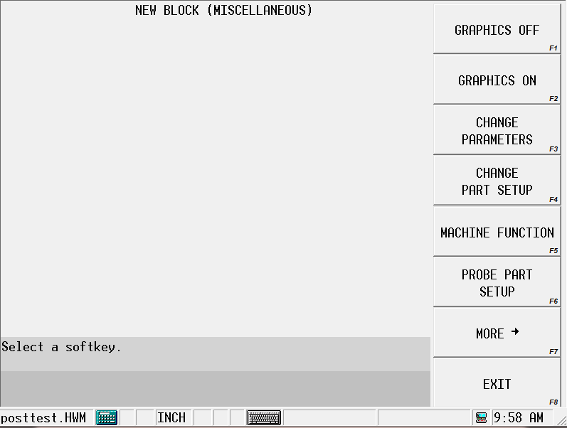
Probe Part Setup Data Block
<For Part Inspection Data Block, see Part Quality Verification.>
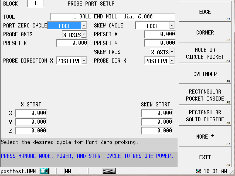
From the New Block (Miscellaneous) screen, press the Probe Part Setup softkey. The Probe Part Setup data block screen appears with fields for programming cycles to determine part zero alone or in addition to determining the skew in the XY plane.
The fields on the left-hand side of the screen and the XYZ Start fields apply to the Part Zero Cycle; the fields on the right-hand side of the screen and the Skew Start fields apply to the Skew Cycle:
Probe Part Setup Fields
The Probe Part Setup screen contains fields for the Part Zero Cycle and the Skew Cycle. The fields change depending on the selected cycle.
Part Zero and Skew Cycles
Refer to the Field Glossary for definitions of the Part Zero and Skew Cycle fields:
|
|
|||
|
|
|||
|
|
|||
|
|
|||
|
|
|||
|
|
Probe Part Setup Data Block Execution
When the program executes this data block, it will automatically probe the part and update Part Zero X, Part Zero Y, Probe Z and X/Y Skew. The data block may be placed anywhere in the part program except within a Pattern.
The Store Results field allows you to specify where you want the probed results to be stored.
-
Part Setup—sends the results to Part Setup.
-
Work Offset—sends the results to the work offset you specify (G54-G59).
-
Aux Offset—sends the results to the Aux Work Offset you specify (1-93).