Mill Face
Face milling directs the cutter path so the tool moves over the rectangular face area of the part, removing material using 60% of the tool diameter from the previous pass (but the last pass may be less).
Axis positioning places the tool over the next cutting path, and cutting resumes in the opposite direction.
To start a new Mill Face block:
-
From the Input screen, select the Part Programming softkey or icon.
-
Select the Insert Block Before softkey.
-
From the New Block screen, select the Milling softkey.
-
From the New Block (Milling) screen, select Face. The Mill Face screen opens.
|
|
Follow this link to hurco.com/connect to view a Mill Face video demonstration: Mill Face video demonstrations on hurco.com/connect Scroll down on the page and select the Intro 4 Mill Face video to download. Internet connection is required. |
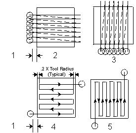
There are four types of face milling, set in the Milling Type field:
-
X Unidirectional—Directs the tool to cut in one direction, parallel to the X axis, and then move the spindle to the retract clearance value. Axis movement occurs at rapid traverse to return the tool to the start point of the next cutting path, which is determined by the system. The start point for each cut is the tool radius plus blend offset away from the starting edge corner.
-
X Bi-directional—Directs the tool to cut in one direction from the start point, parallel to the X axis. Axis positioning occurs to place the tool over the next cutting path, and cutting resumes in the opposite direction. The new cutting path for the tool is automatically determined by the system.
-
Y Unidirectional—Directs the tool to cut in one direction, parallel to the Y axis, and then move the spindle to the retract clearance value. Axis movement occurs at rapid traverse to return the tool to the start point of the next cutting path, which is determined by the system. The start point for each cut is the tool radius plus blend offset away from the starting edge corner.
-
Y Bi-directional—Directs the tool to cut in one direction from the start point, parallel to the Y axis. Axis positioning occurs to place the tool over the next cutting path and cutting is in the opposite direction. The new cutting path for the tool is automatically determined by the system.
|
|
|
1 Blend Offset |
|
|
2 X Unidirectional |
|
|
3 Y Unidirectional |
|
|
4 X Bidirectional |
|
|
5 Y Bidirectional |
The Field Name Glossary contains definitions of all WinMax fields. The fields listed below appear on the Mill Face screen. Fields displayed on screen may vary according to machine type, configuration, parameter settings, and/or settings in other fields.
|
|
|||
|
|
|||
|
|
|||
|
|
|
||
|
|
|
||
|
|
|
||
|
|
|