Part Quality Verification
Part Inspection data blocks are available with the Probing Option for performing part quality verification. This section describes the Part Inspection data blocks.
Part Inspection
A Part Inspection data block is available to monitor real-time data for selected probing cycles. When the data block is executed, the software creates two files: progname.txt and progname.dat, where “progname” is the name of the part program.
The files are stored on the hard drive in the same sub-directory as the part program file and contain time-stamped information about the selected geometry.
The information in the files can be used for reports and part quality verification. Both files contain the same information and are available for you to view.
-
progname.txt - contains ASCII text, viewable with any editor.
-
progname.dat - contains a comma delimited file that may be imported to a spreadsheet.
Part Inspection Cycles
To access the Part Inspection cycles, follow this softkey sequence from the Input screen:
-
Select PART PROGRAMMING.
-
Select MISCELLANEOUS.
-
Select MORE. This screen appears:
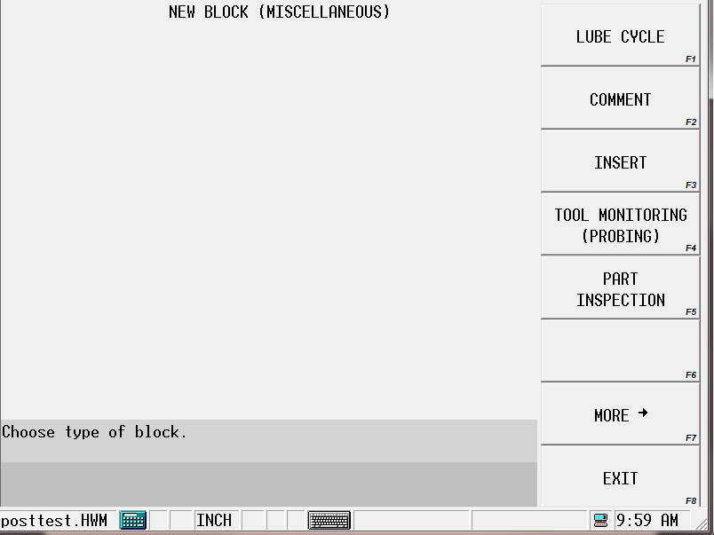
Select the PART INSPECTION (F5) softkey and this screen appears:
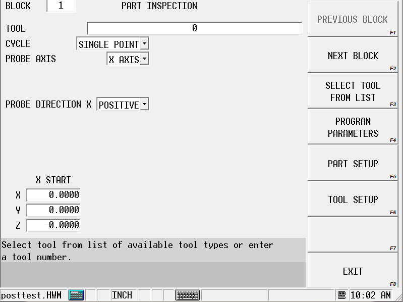
Part Inspection Fields
The fields on the Part Inspection screen change depending on the selected cycle and are defined as follows; refer to the Field Glossary for definitions of the Part Zero Cycle fields:
|
|
|||
|
|
|||
|
|
|||
|
|
|
||
|
|
|
||
|
|
|
Part Inspection Programming
Follow these steps to program a Part Inspection data block:
-
Enter the part probe tool number in the tool field.
-
When the cursor is on the Inspection Cycle field, the softkeys change. Select a cycle type for the Inspection Cycle field.
-
Program the remaining fields as described in the “Part Inspection Fields” section. The data block is stored with the program and executed automatically.
Part Inspection Files
When the Part Inspection data block is executed, the software automatically creates the part inspection files. The position data is presented in part relative coordinates.
-
To view the files on your PC, first copy them to a disk in the floppy drive. Follow the steps for saving files to disk in the Programming Basics chapter of the Getting Started with WinMax manual.
|
|
It is not possible to view the Part Inspection files on the CNC. |
Here is a sample Part Inspection Probe.txt file:
******************************************
* PART INSPECTION DATA *
******************************************
Cylinder inspection (block # 3) executed 15:46:58 8/10/2000
Part Count = 4
Center Diameter
******************************* ****************************
X 16.7168 inches ( 424.607 mm) 1.8878 inches ( 47.951 mm)
Y 10.0995 inches ( 256.527 mm)
Single point inspection (block # 3) executed 9:50:31 8/11/2000
Part Count = 5
Point
*******************************
X 10.3365 inches ( 262.548 mm)
Y 10.3882 inches ( 263.860 mm)
Z 14.2154 inches ( 361.070 mm)
Hole/circle inspection (block # 4) executed 9:50:45 8/11/2000
Part Count = 5
Center Diameter
******************************* ****************************
X 9.3299 inches ( 236.978 mm) 2.7577 inches ( 70.045 mm)
Y 15.4572 inches ( 392.612 mm)
Cylinder inspection (block # 5) executed 9:51:02 8/11/2000
Part Count = 5
Center Diameter
******************************* ****************************
X 16.7171 inches ( 424.613 mm) 1.8883 inches ( 47.962 mm)
Y 10.0996 inches ( 256.531 mm)
Rectangular pocket inspection (block # 6) executed 9:51:24 8/11/2000
Part Count = 5
Center Length
******************************* *******************************
X 14.4527 inches ( 367.099 mm) X 4.7259 inches ( 120.037 mm)
Y 14.3001 inches ( 363.223 mm) Y 4.7258 inches ( 120.034 mm)
Rectangular solid inspection (block # 7) executed 9:51:47 8/11/2000
Part Count = 5
Center Length
******************************* *******************************
X 9.4447 inches ( 239.895 mm) X 3.8176 inches ( 96.967 mm)
Y 12.1092 inches ( 307.575 mm) Y 1.2629 inches ( 32.079 mm)
Plane intersect inspection (block # 8) executed 9:52:08 8/11/2000
Part Count = 5
Corner
*******************************
X 7.7663 inches ( 197.264 mm)
Y 13.2841 inches ( 337.417 mm)