3D Mold
3D Mold creates a three dimensional part. Requires the 3D Mold option.
|
|
For Swept Surface programming, see Swept Surface in the Milling chapter of the Conversational Programming manual. |
3D Mold Parameters
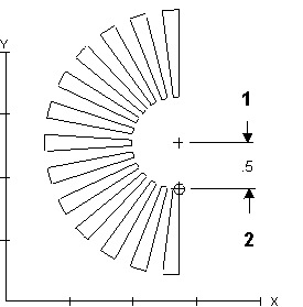
To create a three-dimensional (3D) part, define a two-dimensional (2D) profile in either the XY or XZ plane (these are the 3D mold parameters). Repeat the 2D profile along a straight line (translate) or repeat it around a centerline (revolve) to produce the final 3D shape (the 3D mold contour). Choose Draw 2D Contour to draw the original 2D contour that will be manipulated using the 3D operations.
To start a new 3D Mold data block:
-
From the Input screen, select the Part Programming softkey or icon.
-
Select the Insert Block Before softkey.
-
From the New Block screen, select the Milling softkey.
-
From the New Block (Milling) screen, select 3D Mold. 3D Mold screen opens.
Combine of any of the three types into composite contours to machine complex parts:
-
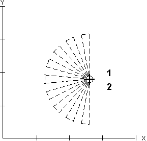
XY Revolved About X (About X)—Use a 2D contour programmed in the XY plane and revolve it about a centerline on the X axis to produce the finished 3D contour.
-
XZ Revolved About Z (About Z)—Use a 2D contour programmed in the XZ plane and revolve it about a centerline on the Z axis to produce the finished 3D contour.
-
XZ Translated in Y (Trans Y)—Use a 2D contour programmed in the XZ plane and translate it in the Y axis.
Select the Edit 3D Mold Contour softkey to access the contour segments. Use the Edit 3D Mold Parameters softkey to reach the parameters screen from any of the contour screens.
The Field Name Glossary contains definitions of all WinMax fields. The fields listed below appear on the 3D Mold Parameter screens. Fields displayed on screen may vary according to machine type, configuration, parameter settings, and/or settings in other fields.
|
|
|||
|
|
|||
|
|
|||
|
|
|||
|
|
|
|
|
|
|
|
1 X Centerline = 0 |
|
|
2 Y Centerline = 5 |
|
|
|
|
|
|
|
|
|
|
|
|
1 X Centerline = 0 |
|
|
2 Y Centerline = 0 |
|
|
|
|
|
|
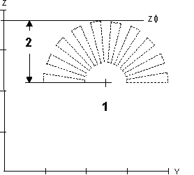
The Centerline Z field determines the Z axis position of the X axis centerline. Changing the Z axis centerline moves the X axis centerline above or below the part surface. This alters the depth of the 3D contour. The Z axis centerline is used only for XY Revolved About X.
To machine the 3D contour below the part surface, enter a negative value in the Centerline Z field. This value is equal to the radius of the part measured from the Y centerline.
Here is a convex contour programmed below the part surface:
|
|
|
|
|
|
1 Original Profile |
|
|
2 Z Centerline |
|
|
|
|
|
|
Determine the length of the 3D contour along the Y axis for XZ Translated in Y, as shown in the example below:

|
|
|
1 Part Zero |
|
|
2 Y Start |
|
|
3 Y End |
|
|
|
|
|
|
3D Mold Contour
|
|
For Swept Surface programming, see Swept Surface in the Milling chapter of the Conversational Programming manual. |
|
|
For Lettering Along Contour programming, see Stick Lettering Along Contour or True-Type Lettering Along Contour in the Milling chapter of the Conversational Programming manual. |
Used in conjunction with 3D Mold Parameters to mill a 3D Mold, program the part surfaces as a 2D profile in either the XY or XZ plane.
The Start Segment number is always 0. Use segments to program lines and arcs which create a contour. Repeat the 2D profile along a straight line (translate) or repeat it around a centerline (revolve) to produce the final 3D shape. The Contour End block marks the end of the programmed contour.
Select the Edit 3D Mold Parameters softkey to access the parameters screen. The Edit 3D Mold Parameters softkey is not available when the cursor is in either the Block or Segment field. When you select the Edit 3D Mold Parameters softkey, it changes to Edit 3D Mold Contour. This softkey is not available when the cursor is in the Block field.
3D Mold Start Segment
See the Field Glossary for definitions of the 3D Mold Contour Start segment fields:
Continue programming the contour by using the Page Down key or by selecting the Next Segment softkey.
Line, Arc, and Blend Arc softkey choices appear.
|
|
A contour can also be created by pasting an existing contour into the program, using Multiple Block Functions on the Program Review screen. This allows you to use the same segments for a Mill Contour Block and a 3D Mold Block without entering each segment twice.
|
3D Mold Line
|
|
For Swept Surface programming, see Swept Surface in the Milling chapter of the Conversational Programming manual. |
Use the 3D mold Line Segment block to create the geometry for a 3D Mold Line segment.
Some 3D Mold Line fields are automatically calculated with the Auto-Calc feature. See Automatic Calculations for more information. Use the Store Calculated Value softkey to retain a calculated value.
See the Field Glossary for definitions of the 3D Mold Line segment fields:
Some fields on screen will vary depending on the type of contour selected.
3D Mold Arc
|
|
For Swept Surface programming, see Swept Surface in the Milling chapter of the Conversational Programming manual. |
Some 3D Mold Arc fields are automatically calculated with the Auto-Calc feature. See Automatic Calculations for more information. Use the Store Calculated Value softkey to retain a calculated value.
See the Field Glossary for definitions of the 3D Mold Arc segment fields:
|
|
|||
|
|
|||
|
|
|||
|
|
|||
|
|
|
Some fields on screen will vary depending on the type of contour selected.
3D Mold Blend Arc
|
|
For Swept Surface programming, see Swept Surface in Conversational Programming. |
A blend arc is an arc that joins two other segments and is tangent to both. Use a blend arc to join two line segments, to join a line segment and an arc segment, or to join two arc segments. The segments to be joined must have a theoretical point of intersection.
If the only information known about an arc is its radius, it is easier to program it as a blend arc if the segments intersect.
Some 3D Mold Blend Arc fields are automatically calculated with the Auto-Calc feature. See Automatic Calculations for more information. Use the Store Calculated Value softkey to retain a calculated value.
See the Field Glossary for definitions of the 3D Mold Blend Arc segment fields:
Some fields on screen will vary depending on the type of contour selected.
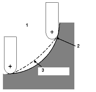
Roughing and Finishing Tools
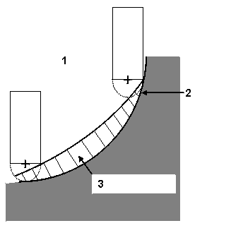
In many applications, a Flat End Mill can be used for roughing, followed by a Ball-Nosed End Mill, which is required for cutting the finished surface.
|
|
|
1 First Data Block Using a Flat End Mill |
|
|
2 Programmed Contour |
|
|
3 Material to be Removed by Ball-Nosed End Mill |
|
|
|
|
|
|
|
|
|
1 2nd Data Block using a Ball-Nosed End Mill |
|
|
2 Programmed Contour (Same Contour as DB1) |
|
|
3 Material to be Removed by Ball-Nosed End Mill |
|
|
|
|
|
|
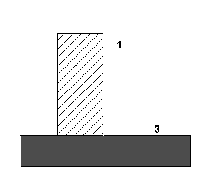
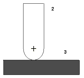
Flat End Mill - the cutter path is computed as if a Ball-Nosed End Mill is used. This computation allows a Flat End Mill to be used for roughing without gouging the part, and in most cases leaves enough material to be removed for the finished surface using a Ball-Nosed End Mill.
|
|
|
1 |
Tool Calibrated on Tip |
|
2 |
Tool Calculated as center of imaginary ball nose |
|
3 |
Tool Zero |
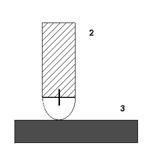
Ball-Nosed End Mill - the system computes the compensated cutter path of the ball center:
|
|
|
1 |
Tool Calibrated on Tip |
|
2 |
Tool Calculated as center of ball nose |
|
3 |
Tool Zero |
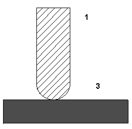
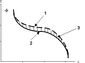
Roughing and Finishing Passes
The Flat End Mill tool path is calculated as a Ball-Nosed End Mill for the roughing pass.
The maximum additional material remaining on the overall 3D contour will not exceed the tool's radius.
|
|
|
1 Roughing contour using Flat End Mill |
|
|
2 Finishing contour using Ball-Nosed End Mill |
|
|
3 Extra Material |
|
|
|
|
|
|