Tool Probing in Zero Calibration Mode
In Zero Calibration mode, the tool is probed and the Zero Calibration and Diameter Wear values are calculated.
|
|
The probe must be setup and calibrated before proceeding. This is done only once, unless the probe is replaced or relocated. For more information see, Appendix A: Tool Probe Setup and Appendix B: Tool Probe Calibration. |
Set the Probing Parameters—Zero Calibration mode
The tool information for the tool(s) to be probed and the probing cycle information is entered in Tool Setup:
-
From the Input screen, select the Tool Review softkey, then the Tool Setup softkey.
-
Select the number of the tool you will be probing, or enter a number and type, if it is a new tool.
-
Enter other parameters as necessary to define the tool. For more information, see Tool Setup Fields.
-
Select the More softkey to access the second set of Tool Setup softkeys.
-
Select the Tool Probing softkey. The Tool Probing screen opens:
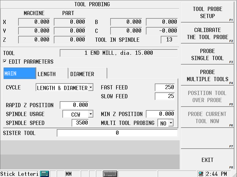
The current tool is displayed in the Tool field. The cycle parameters are displayed but are read-only. Parameter default values are set in the Tool Probing Cycle Defaults screen, see Tool Probing Cycle Defaults. If you need to change one or more parameters for the current tool, check the Edit Parameters check box. (If you need to change a parameter for all tools, go back to the Tool Probing Cycle Defaults screen and make the change there.) The defaults should be set before proceeding with the probing cycle.
To set the remaining cycle parameters for the current tool:
-
Select the type of probing cycle from the drop-down list in the Cycle field:
-
Length—measures the tool length (as Zero Calibration). This value is automatically calculated using the stored internal value and the Probe Z value obtained from probe calibration.
-
Diameter—measures the actual tool diameter, and uses this value to determine the Diameter Wear. For more information, see the Diameter Wear definition in Tool Setup Fields.
-
Length & Diameter—measures both length and diameter.
-
-
Ensure the correct value has been entered in the Rapid Z Position field. This is the position just above the contact point of the probe that the tool rapids down to before continuing downward at Fast Feed for the initial touch.
-
Specify the Min Z Position. This is the lowest position that Z will be allowed to travel during the probe cycle.
-
Indicate Yes or No for Multi Tool Probing. Yes will include the current tool in multi-tool probe cycle.
-
Specify a Sister Tool to be used for as a replacement if tool wear is out of tolerance. See Tool Quality Monitoring.
-
The Length and Diameter tabs contain the values for these parameters set in the Tool Probing Cycle Defaults screen, and may be changed here for the current tool; check the Edit Parameters check box.
Refer to the Field Glossary for definitions of the Tool Probing Parameters:
|
|
||
|
|
||
|
|
||
|
|
||
|
|
||
|
|
Determine Probe Z
The Probe Z value of the part needs to be set whenever a new part is placed on the table. The Zero Calibration value of the tool is calculated using the new Probe Z value, the stored internal value (from tool probe calibration), and the probed tool length.
If you are using a reference tool to calibrate the tool probe:
-
From the Input screen, select the Part Setup softkey to open the Part Setup screen.
-
With the cursor in the Probe Z field, touch off the top of the part with the part probe or reference tool.
-
Select the Store Machine Position softkey. This value is stored in Probe Z.
If you are using a part probe to calibrate the tool probe, use the part probe Z Edge cycle to determine Probe Z. See Edge in Part Probing.
Tool Probing Cycle Defaults
Defaults for probing cycle parameters that infrequently need to be changed are set and stored in the Tool Probing Cycle Defaults screen. Once these parameters are set, they are automatically applied to each tool and do not have to be accessed again. However, if it is necessary to change one or more parameters for a specific tool, this is done in the Tool Probing screen. To access the Tool Probing Cycle Defaults screen:
-
From the Tool Probing screen, select the Tool Probe Setup softkey. The Tool Probe Parameters screen opens.
-
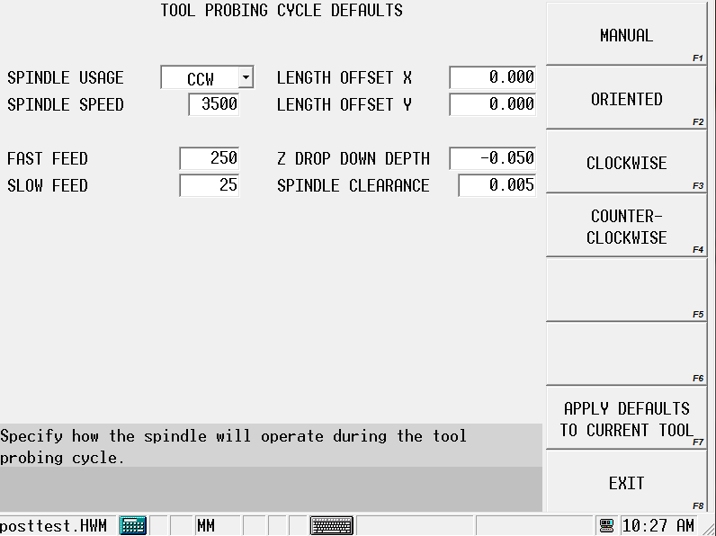
Select the Tool Probing Cycle Defaults softkey. The Tool Probing Cycle Defaults screen opens. Set the default values in this screen.
-
Select the Spindle Usage. This is the direction the spindle turns during the probe cycle.
-
Enter a Spindle Speed, if Spindle Usage is CW or CCW.
-
Specify the Fast Feed and Slow Feed. These are the feedrates of the initial touch (Fast) and measurement touch (Slow).
-
Specify the X and Y Length Offsets, if probing for length of a tool with its cutter offset from the center, for example, a face mill. Otherwise, leave at 0.0.
-
Specify Z Drop Down Depth for diameter. This is the distance the tool drops down from the point where the tool tip touches the top of the probe, when probing for diameter. Value is always negative.
-
Specify Spindle Clearance, the distance between the tool and the probe when the tool drops down for diameter probing.
Select the Apply Defaults to Current Tool softkey to apply these defaults to the tool currently being edited. You only need to do this when you first set the defaults or when you change any of the values.
Select Exit twice to return to the Tool Probing screen.
Run the Probe Cycle
When the Probe Z value is set, return to the Tool Setup/Tool Probing screen
-
Select the Probe Single Tool softkey.
|
|
If the tool that you wish to probe is already in the spindle, select the Probe Current Tool softkey. To probe multiple tools, see Probe Multiple Tools. |
-
Enter the Tool Number to probe. The following sequence occurs for length probing:
-
The Start Cycle button flashes and a prompt to press Start appears.
-
Press the Start Cycle button to continue.
-
If the tool to be probed is not in the spindle, a tool change occurs.
-
If the tool to be probed is not in the magazine, the software prompts for the tool.
-
The spindle operates as specified in the Spindle Usage field in Tool Setup.
-
-
The Z axis moves downward at rapid feed until it reaches Rapid Z Position. Axis Feedrate Override is active during this move.
-
The Z axis continues moving at Fast Feed until a probe deflection occurs.
-
If the probe reaches Min Z Position prior to deflection, an error message appears. The value may need to be adjusted to correct the problem.
-
-
The tool touches the probe (or breaks the beam for laser).
-
For a touch probe:
-
The tool retracts slightly (at Slow Feed) and makes three touches (deflections) at Slow Feed. The average length of these deflections is used to determine the tool length.
-
-
-
The Probe Single Tool cycle is now complete for length. Select the Exit softkey to return to the initial Tool Setup screen. The Zero Calibration field is updated and the “P” designator appears. Continue with the next step to probe the tool’s diameter.
-
If you entered an estimate of the tool’s diameter in the Diameter field and selected Diameter or Length & Diameter in the Cycle field on the Tool Probing screen, the probe cycle continues with the tool Diameter sequence:
-
The tool retracts just above the probe and moves to one side at Spindle Clearance.
-
The tool drops down to Z Drop Down Depth, below the top of the tool probe stylus or beam, and moves toward the probe.
-
The tool touches the probe (or breaks the beam for a laser).
-
For a touch probe:
-
The tool retracts slightly (at Slow Feed) and makes three touches (deflections) at Slow Feed. The average of these deflections is stored for calculation after the other side of the tool is probed.
-
-
The tool moves up to Rapid Z Position and over to the other side of the stylus or beam (to Spindle Clearance), and steps a-d are repeated from the other side of the probe.
-
The two readings (one from each side of the probe) are used to determine the actual diameter of the tool.
-
-
The actual probed diameter is subtracted from the tool diameter entered in Tool Setup, and this value appears in the Diameter Wear field on the Tool Setup screen with the “P” designator.
Probe Multiple Tools
The Probe Multiple Tools cycle determines Zero Calibration and/or Diameter Wear (Diameter) based on the setting of the probe cycle field. All tools that are defined in Tool Setup and have Multi-Tool Probing field set to Yes will be included in the multiple tool probing cycle. Any tool that has Multi Tool Probing set to no will be skipped but may still be probed using the single tool cycle.
The tools must be entered in Tool Setup and the probe cycle parameters set; see Set the Probing Parameters—Zero Calibration mode.
Follow these steps to perform a Probe Multiple Tools cycle:
-
Select the Probe Multiple Tools softkey.
-
The following sequence occurs:
-
The Start Cycle button flashes and a prompt requests you to press Start to initiate the multiple tool probing cycle.
-
Press the Start Cycle button to continue. The first tool to be calibrated is determined by the current tool in the spindle, the Cycle field and the value of the Multi Tool Probing field. The control starts with the current tool in spindle and scans in ascending order. A tool must have a Cycle defined (Length, Diameter, or both) and the Multi Tool Probing field set to Yes. The first tool to meet these requirements is placed in the spindle.
-
The tool is probed as described in Run the Probe Cycle.
-
The tools list is scanned again in ascending order until the next tool to meet the multi tool probing criteria is found. A tool change occurs and the tool is probed as described in Run the Probe Cycle.
-
This process repeats until there are no more tools to probe. During the tool scanning when the highest number tool is reached the list wraps around to tool one. The scan continues until the original tool in spindle is reached. When this occurs the multi tool probing cycle is complete.
-
-
Note that once this process begins the operator is no longer required. The entire process is automatic (as long as the tools are in the ATC).