Appendix B: Tool Probe Calibration
The Tool Probe must be calibrated before probing can be performed.
|
|
Probe Calibration must be completed before probing can begin, but they only need to be done one time, unless the probe is relocated or replaced, if the Slow Feed value is changed, or if the tool calibration mode is changed. |
Probe Calibration—Absolute Tool Length mode
To calibrate the Tool Probe:
-
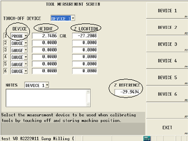
Access the Tool Measurement screen (Tool Setup/More/Tool Measurement Settings softkey):
-
Specify Probe in the Device field.
The Z Reference position must be known to proceed. Z Reference is the distance from the table top to Machine Zero. If already set, skip to step 8.
-
Advance to Z Reference field.
-
Place a gauge of known height on table top.
-
With a reference tool in spindle, jog Z-axis down and carefully touch reference tool to top of gauge block.
-
Select the Store Machine Position softkey or press the store position button on remote jog unit.
-
Subtract the reference tool length and the gauge height from the stored machine position, and manually enter this value in the Z Reference field. For example, if the stored machine position is -300mm, and the reference tool length = 150mm, and the gauge height = 50mm, the Z Reference value is -500mm.
-
Access the Tool Setup screen. Enter the exact tool length for the Reference Tool in the Tool Cal Length field.
-
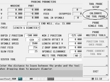
Select the More softkey, and then the Tool Probing softkey. The Tool Probing screen opens.
-
Select Length in the Cycle field.
-
Select the Calibrate the Tool Probe softkey. The control asks for the reference tool (number) to use for calibrating the probe; enter the number and select OK to calibrate the probe.
-
When calibration is complete, the Tool Measurement screen opens and the Height and Z Location fields contain the measured and calculated values:

Now the probe is calibrated and you can proceed to Set the Probing Parameters—Absolute Tool Length Mode.
Probe Calibration—Zero Calibration mode
The tool probe can be calibrated (Z height determined) with a part probe or with a reference tool.
When tools are probed, the Probe Z value and the stored internal value (from the calibration of the tool probe) are used to calculate Zero Calibration. When a new part is placed on the table, a new Probe Z value must be determined.

Calibrate Tool Probe with Part Probe
The Tool Probe can be calibrated (Z height determined) with a Part Probe.
|
|
When using a part probe, Part Probe Parameters and Deflection Offsets must be set before proceeding with tool probe calibration. Part Setup—Part Probe Parameters and Part Probe Deflection Offset Calibration. |
With the part probe in the spindle:
-
From the Tool Setup screen, select the More softkey.
-
Select the Tool Probing Softkey.
-
Set the Rapid Z Position. Use the remote jog unit to jog the part probe to a point just above the contact point of the tool probe and select the Set Position softkey, or type in a value for the Rapid Z Position field. (With the cursor in this field, the Position Tool Over Probe softkey can be used to position the part probe over the tool probe before jogging Z to the desired position.)
-
Select the Calibrate the Tool Probe softkey.
-
Press the flashing Start Cycle button.
The control activates the part probe and the Z axis moves down at rapid, then at Approach Feed until a probe deflection occurs or Minimum Z is reached. (If the probe reaches Minimum Z prior to deflection, an error message appears. Minimum Z is set in the Part Setup Probe Parameters.)
If the appropriate fields are set correctly, then the two probes will touch (or the part probe breaks the beam on a laser tool probe). The part probe will then retract slightly and touch again at the feed rate specified in the Measurement Feed field. The average deflection position is recorded and saved internally for the Zero Calibration value calculation.
Next you must determine the Probe Z value. See Determine Probe Z.
Calibrate Tool Probe with Reference Tool
The Tool Probe can be calibrated (Z height determined) with a Reference Tool.
-
From the Tool Setup screen, select the More softkey.
-
Select the Tool Probing Softkey.
-
Set the Rapid Z Position. Use the remote jog unit to jog the reference tool to a point just above the contact point of the tool probe and select the Set Position softkey, or type in a value for the Rapid Z Position field. (With the cursor in this field, the Position Tool Over Probe softkey can be used to position the reference tool over the tool probe before jogging Z to the desired position.)
-
Select the Calibrate the Tool Probe softkey.
-
A prompt appears requesting the Reference Tool number. Enter the appropriate tool number and select OK.
|
|
If necessary, a tool change occurs, placing the reference tool in the spindle. If the tool is not in the magazine, the software will prompt you for the tool. |
-
Press the flashing Start Cycle button.
The Z axis moves downward at rapid then at Fast Feed until a probe deflection occurs or Minimum Z is reached. (If the probe reaches Minimum Z prior to deflection, an error message appears. Minimum Z is set in the Tool Probing screen.)
The reference tool touches the tool probe, retracts slightly, and touches again at the feedrate specified in the Slow Feed field. The number of slow touches is specified by the Repetitions parameter. The average deflection position is recorded and saved internally for the Zero Calibration calculation.
Next you must determine the Probe Z value. See Determine Probe Z.


