Auto Mode
Programs are run in Auto Mode. Press the Auto button on the console to access Auto Mode to check for errors, compute estimated run time, recovery/restart, perform a dry run, or run a part program.
The following softkeys are available in Auto Mode:
-
Use Editing File—selects the active program file to run. If this softkey is not selected, WinMax defaults to the last program run. If the last program run does not match the program that is being edited (as indicated in status bar), the operator will be prompted to select which program to run.
-
Feed & Speed Optimization—fine tunes program execution, using the Axis Feed Rate and Spindle Speed dials to adjust values. This softkey is disabled in Test Mode.
-
Linear Thermal Compensation—accesses the Linear Thermal Compensation table where parameters are set to manage linear growth. See Linear Thermal Compensation.
-
Check for Errors—checks the program from the Start Block through the End Block and displays error status. The number of the data block containing the error is included in the error message.
-
Compute Estimated Run Time—provides an estimate of time it takes to run the program. Select the Abort Operation softkey to stop computing estimated run time.
-
Recovery Restart—restarts a conversational or NC part program; typically at the point at which the program was interrupted. This softkey is disabled in Test Mode.
-
For Conversational Programs—if necessary, Conversational Start and End blocks can be changed from the default.
-
For Mill Contour data blocks: Recovery Restart only occurs at segment 0 of a Mill Contour data block, not at a segment within a data block.
-
For Pattern data blocks: the user is prompted to specify which pattern or block instance to restart at and to provide any additional restart information for the start block. See Patterns Overview of the Patterns chapter, for more information.
-
-
For NC Programs—use the following softkeys to restart an NC program after it was aborted either by the machine or the operator. Preparatory functions such as coolant, feeds and speeds, and offsets will be executed before machining resumes, and Tool Vector input is checked.
-
Set Restart Marker—manually sets the restart marker. An “R” will appear to the left of the block selected, and will clear if the program successfully runs.
-
Auto Set Restart Marker—automatically marks the last block being executed when the program was stopped, or where an error occurred during error checking.
-
Reset Restart Marker—clears the Restart Marker and cancels the Recovery Restart operation. Can be used on a block after a G41/G42.
-
Set End Marker—indicates the block that system should use to end program verification and execution. An “E” is inserted to the left of the block.
-
Reset End Marker—restores end marker to its default position at the end of the program.
-
-
-
Dry Run—active in Test Run mode only. Performs a program test run to identify potential problems before cutting the part. Specify all or a portion of the part program that will be tested in the Start and End blocks.
|
|
If the Z Start value is set below the stock surface, the Minimum Z value must be programmed so the tool does not plunge into the part. A message appears requesting the Minimum Z value. Note that Minimum Z will be shifted by patterns. |
-
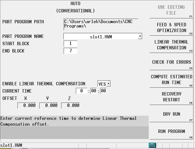
Run Program—initiates program execution and displays monitoring information. Disabled in Test Mode. When selected, the program is buffered and the Start Cycle button flashes. Pressing the Start Cycle button starts the program run. If the machine is not calibrated, the Manual screen immediately displays.
|
|
Changes made to a program while running take effect when the Start Cycle button is pressed again. |
Linear Thermal Compensation
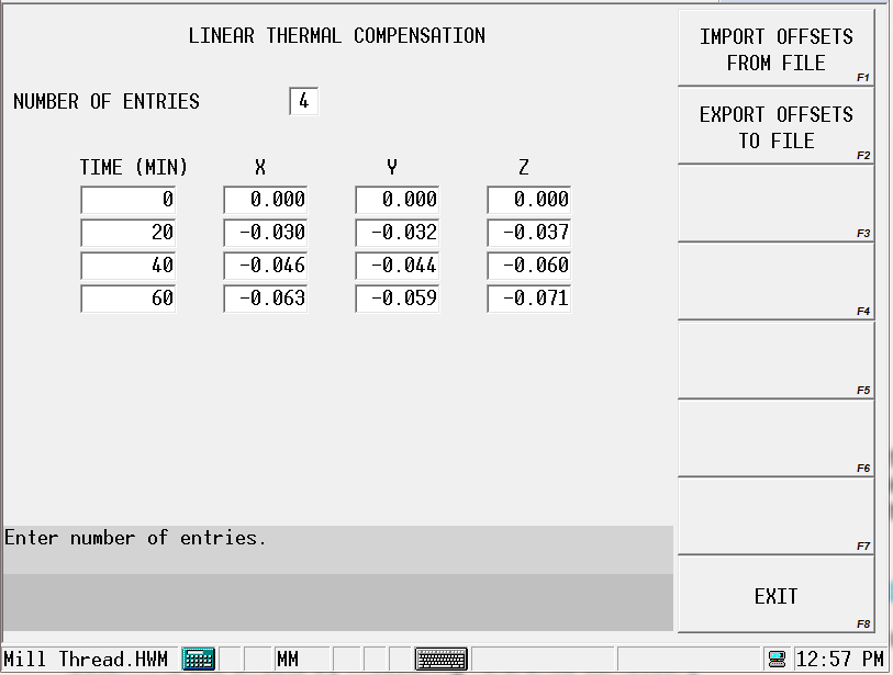
Linear Thermal Compensation parameters allow axis adjustments to compensate for linear growth. Offsets can be set for any linear axis, at specified time intervals, in minutes (up to 99,999,999). Between two and ten entries can be set.
|
|
Since compensation is applied to the machine X-, Y-, and/or Z-axes, it cannot be used to compensate spindle thermal growth on rotary machines when the spindle is not aligned to the machine Z-axis. Compensation values are linearly interpolated between time entries. |
Linear Thermal Compensation is enabled in the Auto Mode screen, where the reference time is set in the Current Time field. Current Time is increased automatically during program run, and is paused when the program is finished. Time and offsets remain unchanged when the program is not running.
Offsets can be imported using the Import Offsets from File softkey. Offsets can be saved/exported using the Export Offsets to File softkey.
Determining Offset Time and Positions for Linear Thermal Compensation
The Linear Thermal Compensation table is part-specific. A gauge or probe can be used to determine the offsets by measuring reference surfaces.
-
Turn off Linear Thermal Compensation (Enable set to NO on Auto Mode screen).
-
Measure reference surfaces.
-
Run part program. At identified intervals (in minutes), quickly measure reference surfaces using same tool or probe, at same locations.
-
Recovery restart the part program.
-
Repeat step 3 and 4 until the part program is finished or measurement values stabilize.
-
Record the intervals (time) and position differences into the Linear Thermal Compensation table.
Auto Mode Monitoring
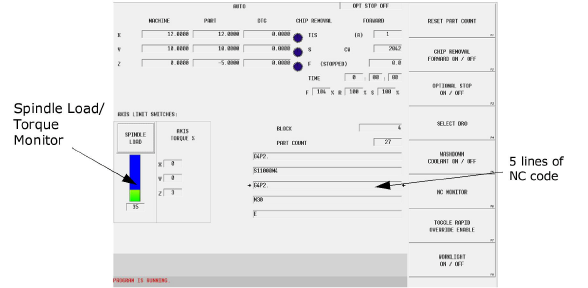
The Auto Mode Monitoring screen appears when the Run Program softkey is selected and program execution begins. Real-time machine and part locations and machine status are shown, as well as Spindle Load/Torque Monitor, the data block and type of operation, and the part count. Select Spindle Load/Spindle Torque to toggle between spindle load or spindle torque monitoring.
For NC programs, five lines of NC code are shown; to view more NC code as the program runs, select the NC Monitor softkey. The bottom portion of the screen is reserved for program status and error messages.
See the Field Glossary for definitions of fields on the Auto mode screens (fields displayed vary depending on machine, configuration, and/or program type):
|
|
These are the monitoring softkeys that may be available for Auto Mode Monitoring:
-
Reset Part Count—Part Count is the number of times a program was executed. To return this value to zero when a new program starts, select the Reset Part Count softkey. A pop-up window opens, where the part count value can be changed or reset to zero.
|
|
Access to the part counter is locked out by Edit Lockout Level “Full,” set in User Interface Settings. See Edit Lockout for information. |
-
Chip Removal Forward On/Off— turn the chip auger in the forward (clockwise) direction on or off. This selection is saved when the Interrupt button is pressed or after the program has finished running. If a stop condition or mode change is made before restarting a new part program or exiting the interrupt cycle, the saved information is cleared. This softkey is only available if your machining center uses a chip auger.
-
Optional Stop On/Off—pauses the program and shuts off the spindle. Optional Stop can be turned On and Off through a soft key in the main menu on the Auto screen while a program is running. When this setting is changed, the new state applies immediately and applies to all programs.
-
Select DRO— view machine, part, distance-to-go, workpiece, and/or transform plane information, displayed in either standard or quad-size DRO view. See Digital Read Out (DRO), below.
-
Coolant Washdown On/Off—turn the coolant washdown on or off for washing chips from the enclosure.
-
NC Monitor—displays a pop-up window containing the current NC code. This feature allows you to view the code as the program runs; the program name appears in the Current Program Name box at the bottom of the monitor. The line of code that is currently being machined is identified in red. When the “Show Modals” boxed is checked, the current active modals are shown. As machining progresses, the monitor will scroll through the lines of code. Select the “Close” button at the bottom of the window to close the NC Monitor.
-
Toggle Rapid Override Lockout—enable or disable overrides to the programmed rapid traverse using the Rapid Override console knob. A confirmation message appears; select Yes to confirm the switch.
-
Worklight On/Off—turn the enclosure worklight on or off. This softkey is only available if your machining center is equipped with an enclosure worklight.
|
|
A (STOPPED) next to FEED indicates that no axis movement is occurring. An (M) next to TOOL IN SPINDLE indicates the tool is a Manual tool. An (A) next to TOOL IN SPINDLE indicates the tool is an Automatic tool. |
Digital Read Out (DRO)
The Auto Run screen uses a standard size digital read out (DRO) at the top of the screen in addition to other fields and information. A Quad-size DRO is available that provides large-view machine, part, or distance-to-go for the part program that is running.
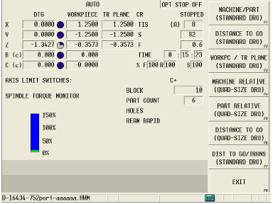
Select the SELECT DRO softkey on the Auto Program Run screen to change the size of the digital read out (DRO). From the Select DRO screen you can see real-time machine information displayed in full-screen view. The softkey menu provides these DRO options:
-
Machine / Part (Standard DRO)—shows real-time axes location relative to machine zero and current part zero.
-
Distance to Go (Standard DRO)—shows real-time axes location relative to machine zero and current part zero, and the remaining distance to completion of move.
-
WorkPC / TR Plane (Standard DRO)—shows real-time axes location relative to machine zero, workpiece zero, and transform plane zero.
-
Machine (Quad-size DRO)—shows in a larger view the real-time axes location relative to machine zero.
-
Part Relative (Quad-size DRO)—shows in a larger view the real-time axes location relative to current part zero.
-
Distance To Go (Quad-size DRO)—shows in a larger view the remaining distance to completion of each move.
-
Dist to Go / Trans (Standard DRO)—shows real-time distance-to-go, and axes location relative to workpiece zero and transform plane zero.
|
|
Use the SELECT DRO softkey to select a different DRO display. |
|
|
A (c) next to the axis indicates the axis is clamped. |
To access the configurable DRO view, select the Auxiliary button, and choose the Launch DRO softkey.
Concurrent Programming
Concurrent Programming allows you to create or edit a program while simultaneously machining a different program. When using Concurrent Programming, two part programs are simultaneously available. To enter Concurrent Programming while machining a part, press the console Input key. The Auto screen is replaced by the Input screen.