UltiPockets
The UltiPocket™ programming option adds special milling routines for machining pocket boundaries with islands. This option provides complete clean out of odd-shaped pockets without cutting the islands programmed inside the boundary. The software automatically calculates the tool path around islands eliminating the long task of plotting these shapes. Islands may also be rotated, scaled, and repeated.
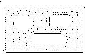
The following drawing shows an inward spiral boundary with three differently shaped islands.
The pocket feature is available for any closed contour data block: Mill Contour, Mill Frame, Mill Circle, Mill Ellipse, Mill Slot, or Mill Polygon.
|
|
To use the UltiPocket feature, first establish the cutter compensation parameter and then program any UltiPocket data blocks.
|

Additionally, see these topics:
Helical Plunge with UltiPockets
Helical Plunge Using Operator Specify Pocket Start
Pocket Boundary
The Pocket Boundary is the outside frame of the part. The basic philosophy of the UltiPocket option is to program the boundary and then tell the system which pockets or islands to avoid within that boundary. This approach eliminates complex calculations and shortens the part programming process.
The types of Pocket Boundaries are Outward, Inward, ADP Zigzag, and ADP 1-Way. These are explained below.
Outward
This selection is only for Circle and Frame data blocks without islands. When this routine is selected, the tool begins from the center region of the part outward to pocket the entire programmed boundary.
To control the percentage of tool engagement during cutting, enter a value in the Step Over field.
Inward
This selection cuts in from the outside of the defined boundary avoiding the defined islands. When this routine is selected, the tool enters the part and begins following a path formed by offsetting the boundary one-half the tool radius, plus the pocket overlap.
To control the percentage of tool engagement during cutting, enter a value in the Step Over field.
After pocketing the boundary, the tool then cuts around the inside of the boundary and the outside of each island, using the selected blend offset and the programmed tool radius.
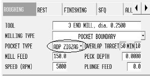
ADP Zigzag
With AdaptiPath (ADP) pocket types the tool makes constant contact with the material surface to decrease cutting time. ADP Zigzag moves the tool in a zigzag pattern; one pass is climb milling, the next pass is conventional milling, alternating climb and conventional passes until complete.
To control the percentage of tool engagement during cutting, enter a value in the Target Step Over field.
For more information, see Climb Milling (Left) and Conventional Milling (Right) in Conversational Programming.
ADP 1-Way
With AdaptiPath (ADP) pocket types the tool makes constant contact with the material surface to decrease cutting time. ADP 1-Way moves only in climb or conventional direction, skimming the part surface on the return move. Climb or Conventional Milling Direction is set in the Program Parameters Milling 1 tab. See Program Parameters in Getting Started with WinMax Mill.
To control the percentage of tool engagement during cutting, enter a value in the Target Step Over field.
For more information, see Climb Milling (Left) and Conventional Milling (Right) in Conversational Programming.
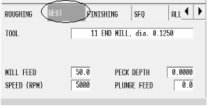
Rest Machining
Rest Machining is available with Pocket Boundary ADP Zigzag and ADP 1-Way. Rest Machining allows you to specify a small tool that is used to clear out remaining pocket areas, i.e., corners where a bigger tool might not be able to reach. The Rest tab appears in the tool data area when either ADP Zigzag or ADP 1-Way pocket types are selected with Pocket Boundary Milling Type on the Roughing tab:
|
|
Programming Islands
After programming the mill data block for a boundary, an island can be defined by creating a Pocket Island data block. As many islands as desired may be defined (subject to computer memory on the control), but all must fit within the defined boundary and should allow the tool to completely define the island.
The island data block can be a Mill Frame, Circle, or Contour (provided it is a closed contour). The Pocket Island data blocks use the standard milling values from the boundary data block and do not display these parameters on the island programming screen. The pocket overlap percentage was also defined in the boundary data block.
Mill Contours
To create a Mill Contour data block using the UltiPocket option, set up the operation in the start segment (segment zero). As in standard WinMax milling, an UltiPocket Mill Contour block consists of segments beginning with segment zero. With the cursor in the MILLING TYPE field, select one of the Pocket options in the Start segment to indicate whether this block is the boundary of the part or one of the islands within the boundary. The boundary must occur first in the program.
The segments after the Start segment are programmed in the same manner as standard milling lines and arcs. Automatic calculation of unknown points is available for these data blocks.
Mill Frame
The Mill Frame data block is often used to create the part boundary.
This block is programmed in the same manner as the standard WinMax Mill Frame, with the addition of the Pocket Overlap percentage.
Mill Circle
The Mill Circle data block is used for both boundaries and islands. It is similar to the standard Mill Circle data block except that if this block is used to create an island, it uses the tool from the boundary data block.
Pattern
Pattern data blocks can be inserted to rotate, scale, or repeat islands. Only Pattern data blocks can be programmed between a boundary data block and an island. As many islands as desired may be defined (subject to available memory), but all must fit within the defined boundary.