Cutter Compensation (preliminary)
Cutter Compensation is set in the Milling Type field in a milling program block.
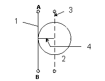
Cutter Compensation allows you to choose the side of the contour the tool should begin cutting. The programmed tool automatically follows the finished contour of the part when cutter compensation is selected. Without cutter compensation, the centerline of the programmed tool follows the print line.
|
1 |
Programmed path |
|
2 |
Cutting tool |
|
3 |
Path compensating for cutter radius |
|
4 |
Cutter radius = amount of cutter compensation offset |
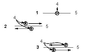
The following diagram shows tool paths using no cutter compensation compared to tool paths using left and right compensation. When either right or left cutter compensation is selected, the tool is offset from the cutting path a distance equal to the tool’s radius. The tool begins cutting at the offset and moves in the selected direction.
|
1 |
No Cutter Compensation |
|
2 |
Cutter Compensation to the left |
|
3 |
Cutter Compensation to the right |
|
4 |
Tool |
|
5 |
Centerline of contour |
The following are the types of cutter compensation used for Mill Contours such as Lines, Arcs, Blend Arcs, Helices, True-Type Lettering, and 3D Blend Arcs:
-
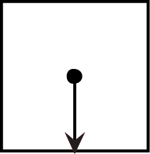
On—Locates the center of the tool on the programmed contour of the frame.
-
Left—Performs climb milling. Refer to Climb Milling (Left).
-
Right—Performs conventional milling. Refer to Conventional Milling (Right).
-
Profile Left—Removes material from a contour for climb milling. Refer to Profile Left and Right.
-
Profile Right—Removes material from a contour for conventional milling. refer to Profile Left and Right.
The following are the types of cutter compensation used for milling Circles, Frames, and Ellipses:
-
On—Locates the center of the tool on the programmed contour.
-
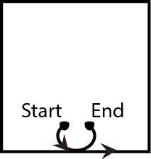
Inside— If Enable Blend Moves is set to YES, the tool enters the part inside the contour and blends into the programmed contour using a 180° arc. Cutter compensation is automatically employed, and the edge of the tool remains inside a programmed contour.
If Enable Blend Moves is set to NO, the tool enters and withdraws from the part inside and tangent to the programmed contour.
-
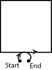
Outside—If Enable Blend Moves is set to YES, the tool enters the part outside the programmed contour, blends into the programmed contour using a 180° arc, and then follows the outside contour. Cutter compensation is automatically employed, and the edge of the tool remains outside the programmed contour.
If Enable Blend Moves is set to NO, the tool enters and withdraws from the part outside and tangent to the programmed contour.
-
Profile Inside—If Enable Blend Moves is set to NO, the tool enters the part inside and tangent to the programmed contour. Cutter compensation is automatically employed, and the edge of the tool remains inside and tangent to the programmed contour. The direction the tool travels depends upon the Milling Direction. The tool is withdrawn from the part inside and tangent to the programmed contour.
If Enable Blend Moves is set to YES, the tool enters the part inside the tool path and blends into and out of the programmed contour using a 180° arc, similar to the Inside milling type, except the Step Over (%) and Max Offset may be added. Refer to Step Over (%) and Maximum Offset for more information.
-
Inside Tangent —The tool enters the part inside and tangent to the programmed contour. Cutter compensation is automatically employed, and the edge of the tool remains inside and tangent to the programmed contour. The direction the tool travels depends upon the Milling Direction. The tool is withdrawn from the part inside and tangent to the programmed contour. Max Offset, Step Over (%), and Enable Blend Moves may not be used.
-
Profile Outside—If Enable Blend Moves is set to NO, the tool enters the part outside and tangent to the programmed profile. Cutter compensation is automatically employed, and the edge of the tool remains outside and tangent to the programmed contour. The direction the tool travels depends upon the Milling Direction. The tool is withdrawn from the part outside and tangent to the programmed contour.
If Enable Blend Moves is set to YES, the tool enters the part outside the tool path and blends into and out of the programmed profile using a 180° arc, except the Step Over (%) and Max Offset fields may be added. Refer to Step Over (%) and Maximum Offset for more information.
-
Outside Tangent—The tool enters the part outside and tangent to the programmed contour. Cutter compensation is automatically employed, and the edge of the tool remains outside and tangent to the programmed contour. The direction the tool travels depends upon the Milling Direction. The tool is withdrawn from the part inside and tangent to the programmed contour. Max Offset, Step Over (%), and Enable Blend Moves may not be used.
-
Pocket Boundary—the tool cuts the part around the programmed boundary and avoid any programmed islands or pockets.
-
Pocket Type—The Pocket Type field appears with Inward and Outward softkey and drop-down list box choices when Pocket Boundary or Pocket Island is chosen for Milling Type. The choices define whether spindle movement spirals from inside the pocket or outside the pocket.
-
Outward—the tool begins cutting operations in the center region of the pocket and cut outward to the edge of the programmed boundary. Outward is used only for Circle and Frame data blocks without islands.
-
Inward—the tool cuts in from the outside of the defined boundary, avoiding the defined islands.
-
-
-
Pocket Island—Defines islands within pockets on a part. As many islands as desired may be defined (subject to available memory), but all must fit within the defined boundary and must allow the tool to completely define the island. A Pocket Island cannot follow an Outward Pocket Boundary.
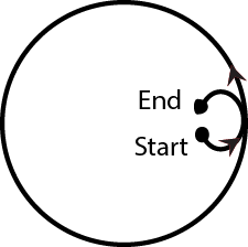
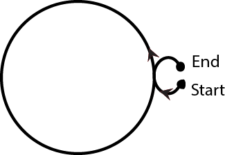
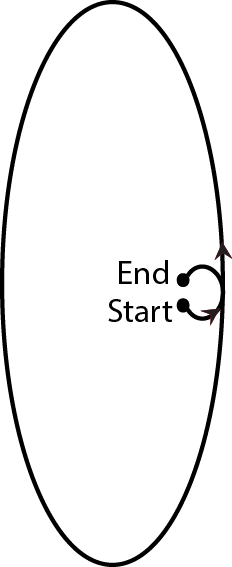
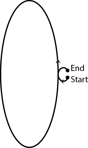
The order in which segments are programmed determines the direction the tool moves from the start point. Setting Conventional (right) or Climb (left) in Milling Parameters overrides the direction of the programmed path.
Unless the Blend Offset is set for 0.0 in Milling Parameters, the system automatically creates Lead In and Lead Out arcs for closed contours. Refer to Lead In/Out Moves.
Circle
|
Centerline |
Inside (with Blend Moves) |
Outside (with Blend Moves) |
Profile Inside (No Blend Moves) |
Profile Outside (No Blend Moves) |
|
|

|
|
|

|

|
|
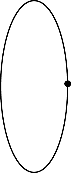
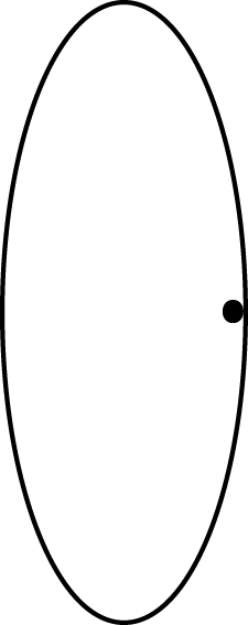
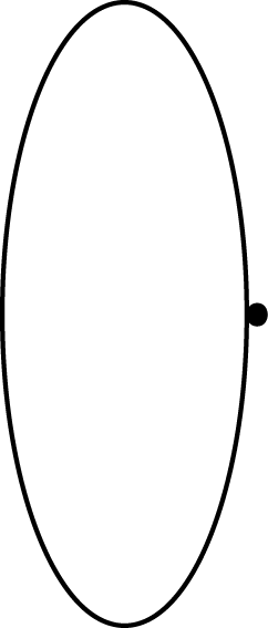
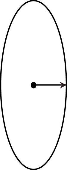
Ellipse
|
Centerline |
Inside |
Outside |
Inside |
Outside |
|
|
|
|
|
|
|
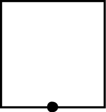
Frame
|
Centerline |
Inside (with Blend Moves) |
Outside (with Blend Moves) |
Profile Inside (No Blend Moves) |
Profile Outside (No Blend Moves) |
|
|
|
|

|

|
|
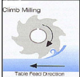
Climb Milling (Left)
Climb milling is the preferred method of cutter compensation, except when the fixturing is not rigid. In climb milling, the tool cuts in the same direction as the feeding motion. This is also known as “in–cut” or “down milling.”
During climb milling, the spindle turns in a clockwise direction. The tool is on the left-hand side of the cut.
The advantages of using climb milling are as follows:
-
The chip starts thick and allows easy penetration into the surface of the part, causing less tool wear and less power consumption.
-
The tool force cuts in and down on the part, helping to hold the part in the fixture. The more rigid the fixture, the better the hold on the part.
-
Chip removal is greater, and there is less re-cutting of chips or marring of the part surface.
-
The cutting fluid is more accessible to the cutting surface.
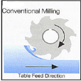
Conventional Milling (Right)
During conventional milling, the cutting teeth move in the opposite direction to the feeding motion. This is known as “out–cut” or “up milling.” When using conventional milling with a clockwise spindle direction, the tool is on the right-hand side of the cut.
The advantages of using conventional milling are as follows:
-
The chip thickness starts at zero, causing less impact on the cutting teeth. This is ideal for setups that are not very rigid.
-
The backlash in older machines is greatly diminished.
|
|
The programming sequence of Lines and Arcs segments determines the cutting direction. However, when programming Mill Frames, Circles and Ellipses, the cutting direction is determined by the values entered in Program Parameters. |

Profile Left and Right
Profile Left and Profile Right work the same as Left (Climb) and Right (Conventional) milling, except that a Max Offset may be added.
Maximum Offset
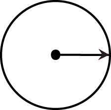
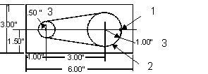
The Max Offset field appears when either Profile Left, Profile Right, Profile Inside, or Profile Outside is selected. Max Offset allows the cutter to be programmed to start at some specific distance away from the programmed profile and move toward the finished profile, using the Step Over parameter, as each pass is completed. It is typically the radius of the largest inscribed circle minus the tool radius. Manually calculate the value and enter it into this field.
|
|
Drawing the part on the graphics screen is the key to determining an optimum Maximum Offset value. |

If a .500" diameter (.25" radius) End Mill is used to machine the part illustrated below (a circle with a 1" radius), the value for the Maximum Offset field is 0.75".
|
1 |
Starting point for the tool |
|
2 |
Largest inscribed circle in this contour |
|
3 |
Radius |
If the tool diameter is changed (i.e., the cutter is sharpened to a smaller diameter), the Maximum Offset value must be manually re-calculated and this new value programmed into Segment 0 of the Mill Contour's Start block. Refer to Lines and Arcs (Mill Contour). The Tool diameter is programmed in Tool Setup and cannot be changed in Part Programming. See Tool Setup in Getting Started with WinMax Mill for more information.