Drill Operations
Select the Drill Operations softkey on the New Hole Operation screen to select the type of drilling operation. The appropriate screen appears with fields describing the operation. The drill operations are:
|
|
See Bore and Ream Operations for information about bore and ream. |
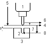
The diagram below shows the relationships of the field names to positions of the tool to the work piece:
|
1 Head |
|
2 Part |
|
|
3 Table |
|
|
4 Z Start Plane |
|
|
5 Rapid Traverse |
|
|
6 Retract Clearance Plane |
|
|
7 Plunge Feed |
|
|
8 Z Bottom |
Be aware of the drill bits' characteristics. The system does not keep track of the type and length of flutes on the bits or the shapes of drills with pilots or other multiple-diameter drills.
This is the machine motion in a basic drilling operation:
-
The table moves at the rapid traverse rate to the programmed X and Y dimensions.
-
The Z axis moves at the rapid traverse rate to the programmed retract clearance.
-
When these coordinates are reached, the Z axis moves at the rapid traverse rate to Z Start.
-
Then the Z axis moves at the programmed plunge feed rate until reaching the Z Bottom dimension.
-
The Z axis dwells the time specified and rapid traverses to the retract clearance.
The rapid traverse rate, retract clearance, and drill dwell are selected in Program Parameters or Change Parameters.
When all values are programmed, the Bolt Circle and Locations softkeys are available. See Bolt Circle and Locations for more information.
Drill
Use a drill to create holes that may be complete or may be used as the starting points for additional drilling operations.
See Drill Fields for field definitions.
Center Drill
Select Center Drill when the work piece is very rigid to create a guide hole for the drilling tool that will be used to complete the hole. Center drilling helps keep holes in their proper locations and prevent runout.
Center drills are special tools with short flutes, but a standard drilling tool may be used to create these starting holes.
See Drill Fields for field definitions.
Counterbore
Use Counterbore to enlarge the end of a previously drilled hole. This operation creates an enlarged area at the end of the hole to accommodate a bolt, cap screw, or pin. These square-shoulder fasteners can then be inserted flush with the top of the part or slightly below the surface of the material.
To avoid unneeded tool changes, use Counterbore before drilling the hole.
See Drill Fields for field definitions.
Spotface
Spotface smooths and squares the surface around a previously drilled hole to provide a seat for a bolt head, a nut, or the shoulders on mating members. The spotfacing operation is a shallow counterboring operation. Spotfacing is often used when the surface of the part is uneven.
To avoid unnecessary tool changes, Spotface can be used before drilling the hole.
See Drill Fields for field definitions.
Countersink
Countersink enlarges the top end of a hole to a cone shape to accommodate the head of a flat or oval headed machine screw. The hole is enlarged so that when the screw is inserted, the screw head will be flush with or slightly below the top of the work piece surface:

See Drill Fields for field definitions.
Gun Drill
Select the Gun Drill feature when using a very long tool and drilling deep holes, as if drilling out the center of a gun barrel. A long, rotating tool may whip off center when approaching the cutting surface, so a drilling cycle that controls the approach to the work piece and corrects positioning of the tool is required.
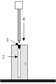
The Gun Drill selection positions the tool without rotating the spindle. This allows the tip of the tool to position precisely in a pre-drilled starting hole, as shown in the diagram below:
|
|
|
|
|
|
1 Work Piece |
|
|
2 Planned Path |
|
|
3 Pre-drilled starting hole |
|
|
4 Long tool moves into position with the spindle off to avoid whipping |
|
|
|
|
|
|
To use the Gun Drill features, perform these tasks:
-
Describe the gun drill tool during Tool Setup.
-
Create a starting hole for the drill as the first step in part programming.
-
Create a Gun Drill data block in the part program.
Each Gun Drill data block must contain at least two operations: one describing the starting hole and one for the gun drill hole.
To create a Gun Drill data block, begin on a New data block screen and follow these general steps:
-
Press the Drill Operations softkey.
-
Create the first operation of the data block by describing the starting hole portion of the data block. Select either the Drill softkey or the Center Drill softkey. Type in the description of the starting hole into the fields displayed on the screen.
-
When all of the starting hole data have been entered, begin the second operation in this data block.
-
Press the Drill Operations softkey and then the Gun Drill softkey.
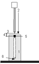
The following illustration shows the Gun Drill program fields as they relate to a part and the drilling tool:
|
|
|
1 Work Piece |
|
|
2 Move at rapid traverse down to Z top |
|
|
3 Z Top |
|
|
4 Z Top Feed—feedrate between Z top and Z Start |
|
|
5 Z Start—spindle begins to rotate at Speed (RPM) |
|
|
6 Z Bottom |
|
|
|
See Drill Fields for field definitions.
Custom Drill
The Custom Drill feature can be used to adjust the feedrate and speed for each step in the drill cycle: entry into hole, break out through bottom of material, bottom, re-entry into hole from bottom, out move at top of hole, and the move to retract clearance plane. Custom Drill is typically used for long hole drill cycles but can be used to customize any drill cycle.
See Drill Fields for field definitions.
Tool Tab
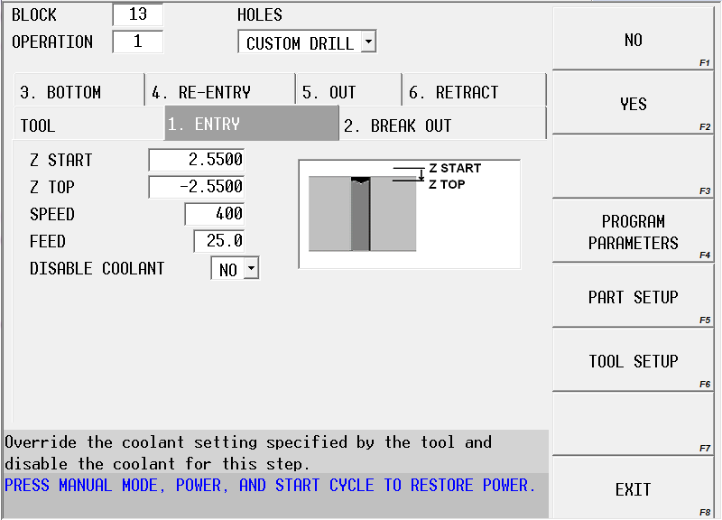
The Custom Drill screen is organized into tabs where the feed, speed, and other parameters are entered for each step of the drill cycle. The first tab is the Tool tab:
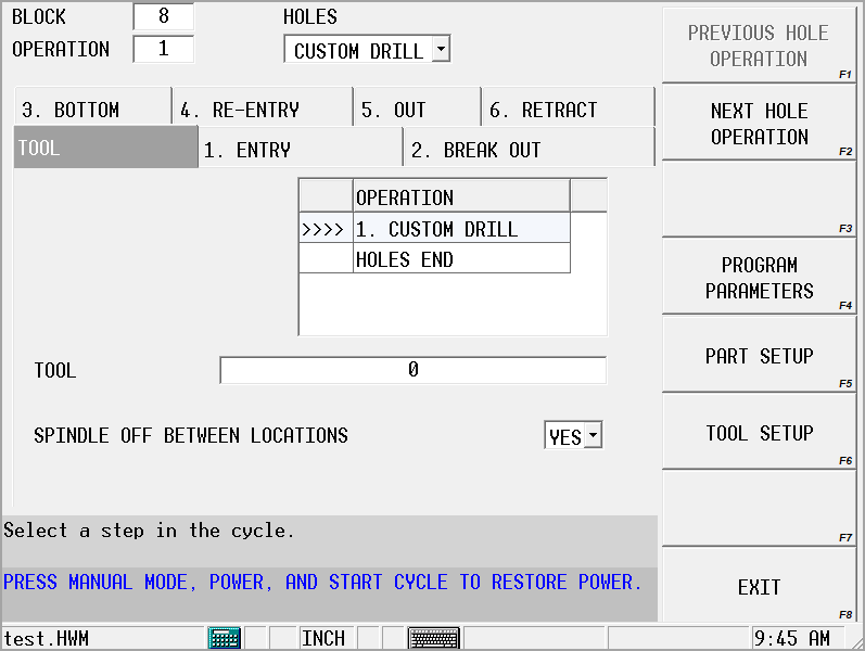
A list of all hole operations are displayed on the Tool tab to show the relation of the Custom Drill cycle with other operations in the block. The tool is specified on this screen.
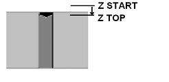
Entry Tab
The Entry step establishes the speed and feed for the approach move starting at Z Start and ending at Z Top. The image shows the move from Z Start to Z Top:
|
|
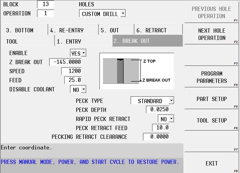
Break Out Tab
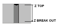
The Break Out tab allows the user to set a feed and speed for the drill operation that differs from the feed and speed used for the move breaking through the bottom of the material (typically to avoid whipping). This step is optional and can be skipped by setting the Enable field to No. When Enable is No, the feed and speed from the Bottom tab are used for the move from Z Top to Z Bottom, and the pecking parameters are set on the Bottom tab.
The image shows the plunge move from Z Top to Z Break Out, if enabled:
|
|
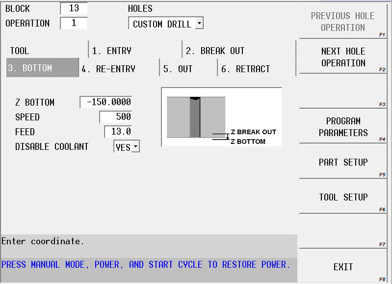
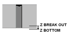
Bottom Tab
The final move through the hole from Z Break Out to Z Bottom is set in the Bottom tab. If the previous Break Out step is not enabled, then the feed and speed set in this step are used for the entire move from Z Top to Z Bottom.
The image shows the motion for the plunge move from Z Break Out to Z Bottom:
|
|
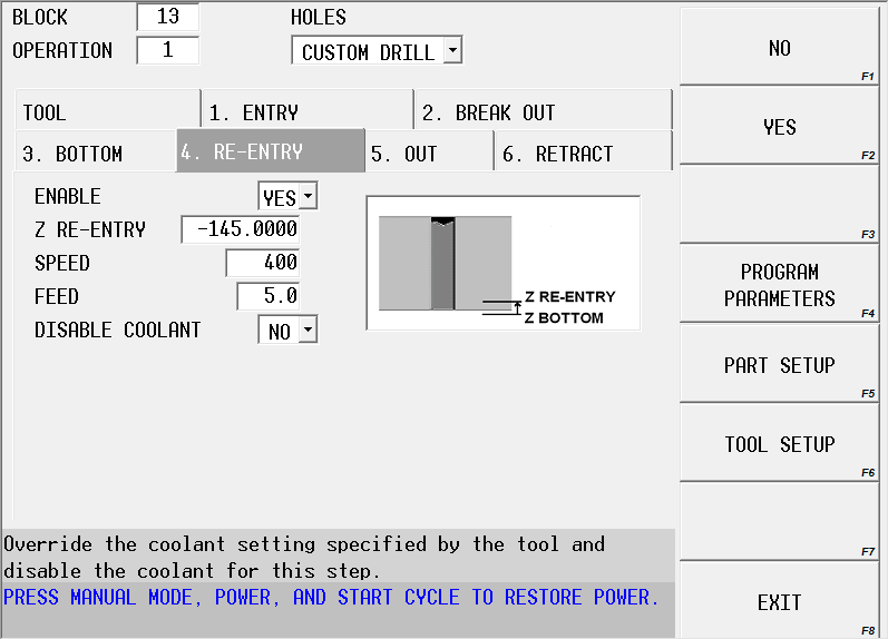
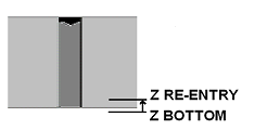
Re-entry Tab
The Re-entry step allows the user to set a speed and feed for the retract move from Z Bottom to a Z position back inside the hole (Z Re-entry). This step is optional and can be skipped by setting the Enable field to No. When Enable is No, the move occurs from Z Bottom to the next enabled step (Out or Retract). If there are no other enabled steps, the spindle moves at rapid out of the hole to the Z start location.
The image shows the move from Z Bottom to Z Re-entry, if enabled:
|
|
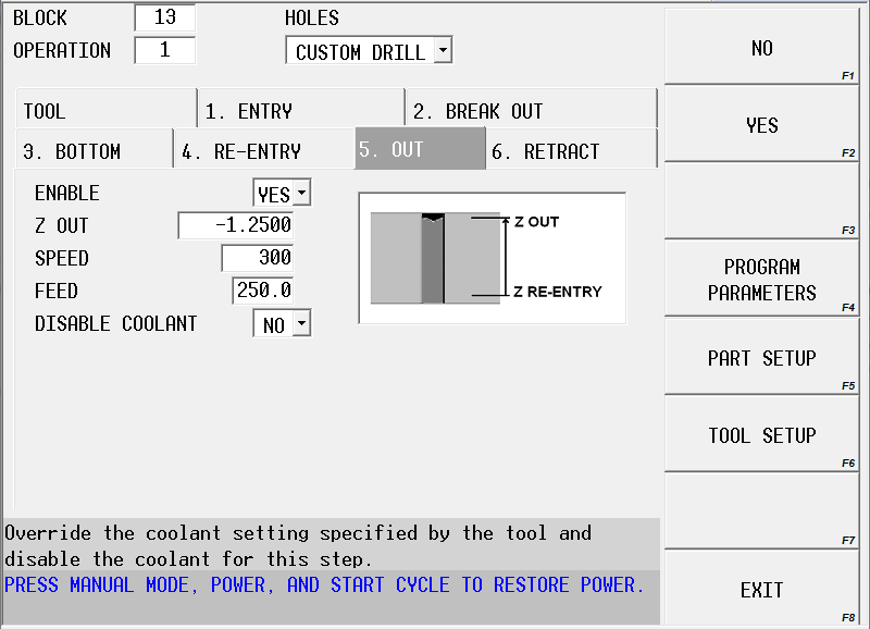
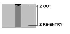
Out Tab
The Out step allows the user to set the speed and feedrate for the retract move from Z Re-entry to Z Out (the Z end position of the retract move from Z Re-entry). This step is optional and can be skipped by setting the Enable field to No. When Enable is No, the move occurs from the last enabled step (Bottom or Re-entry) to the Retract step, if it is enabled. If the Retract step is not enabled, the spindle moves at rapid from the last enable step (Bottom or Re-entry) out of the hole to the Z start location.
The image shows the move from Z Re-entry to Z Out, if enabled:
|
|
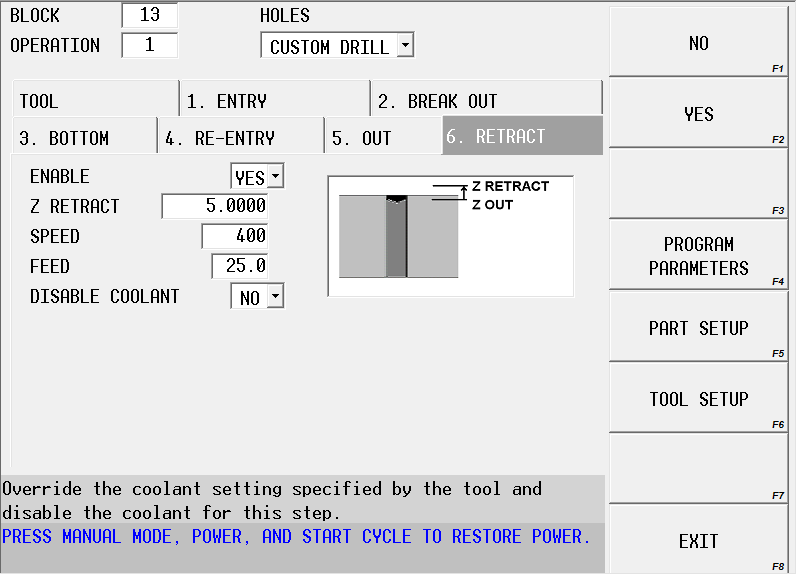
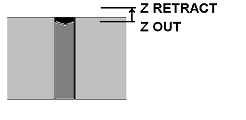
Retract Tab
The Retract step allows the user to set the feed and speed for the move from Z Out to Z Retract. This step is optional and can be skipped by setting the Enable field to No. When Enable is No, the tool moves at rapid feedrate from the last enabled step (Bottom, Re-entry, or Out) to the Z Start position.
From Z Retract, the tool moves at rapid feedrate to the retract clearance plane; therefore, Z Retract should be less than the retract clearance plane. Z Retract can be greater than, less than, or equal to Z Start.
The image shows the retract move from Z Out to Z Retract:
|
|
Drill Fields
See the Field Glossary for definitions of the Drill Operations fields: