Appendix A: Tool Probe Setup
Tool probe setup parameters provide critical information on how the machine will use the probes. The parameters include fields specific to programming a touch probe or a laser probe.
|
|
Tool probe setup parameters should only be adjusted when a tool probe is newly installed, relocated, or when probing feedrates are changed. |
From Tool Setup, select the Tool Probing softkey, then the Tool Probe Setup softkey. The Tool Probe Parameters screen opens. From here, you can access the parameters for the type of probe you select, either Touch Probe or Laser Probe.
Touch Probe Parameters
Select the Touch Probe Parameters softkey to access the touch tool probe fields. The following screen appears:
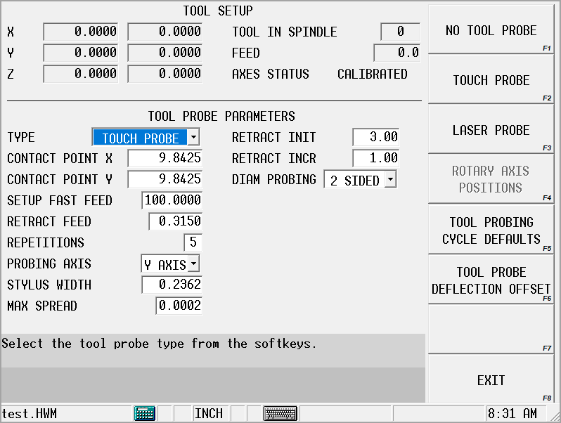
Refer to the Field Glossary for definitions of the Touch Probe Parameters fields:
|
|
|||
|
|
|||
|
|
|||
|
|
Laser Probe Parameters
Select the Laser Probe softkey to access the laser tool probe fields:
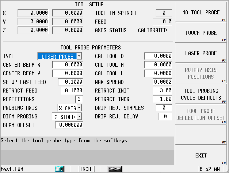
Refer to the Field Glossary for definitions of the Laser Probe Parameters fields:
|
|
|||
|
|
|||
|
|
|||
|
|
|||
|
|
|||
|
|
|||
|
|
|
Laser Beam Calibration
The Laser Beam Calibration cycle uses a tool to probe the beam and determine the exact trigger point position in the light beam for X/Y and Z axes so the light beam can effectively measure tools. The Determine Laser Beam Offset softkey on the Tool Setup Probe Parameters screen initiates the cycle to set the beam offset value. Refer to Appendix A: Tool Probe Setup for field definitions for this screen.
You must calibrate the laser system before using the light beam for measuring tools. The laser calibration tool or precision dowel used for performing calibration is inserted into the spindle just like any tool.
Laser Tool Calibration Calculations
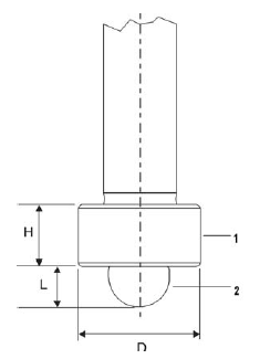
The calibration tool’s dimensions are determined by using a precision dowel or a laser calibration tool, as shown in the figure below. Use this formula to determine the location on the tool’s diameter to interrupt the beam:
Length + (Height / 2) = Point on Diameter to Interrupt Beam
The software uses the Cal Tool D(iameter), H(eight), and L(ength) fields (shown below as D, H, and L) and the trigger points established in this cycle to determine the Center Beam X or Y values, depending on the Probing Axis.
|
|
|
1. Donut |
|
|
2. Tip |
|
|
|
|
|
|
|
|
|
Laser Tool Calibration Cycle
Follow these steps to run the Laser Calibration Tool cycle:
-
Access the Tool Setup Probe Parameters screen using this softkey sequence:
-
Tool Setup softkey
-
More softkey
-
Tool Probing softkey
-
Tool Probe Setup softkey
-
-
In the Type field, select Laser Probe.
-
Enter values in the Cal Tool D, H, or L fields. The DETERMINE LASER BEAM OFFSET softkey appears when the cursor is in any of these fields.
-
Select the DETERMINE LASER BEAM OFFSET softkey and this sequence occurs:
-
The Start Cycle button flashes.
-
Press the Start Cycle button to begin the cycle. The tool moves down in the Z Plane at Setup Fast Feed until the beam is interrupted by the tip of the tool.
-
The tool moves up slightly at Retract Feed until the beam is uninterrupted. This sequence of slow moves into, then out of, the beam repeats for Repetition number of readings. The average switch point coming out of the beam is recorded.
-
The tool moves up slightly again, moves over in the X/Y Plane, and down until the laser beam is positioned parallel to the center of the tool’s donut.
-
The tool moves in the X/Y Plane at Fast Setup Feed toward the beam until the beam is interrupted.
-
The sequence of slow moves into then out of the beam repeats for Repetition number of readings. The average switch point coming out of the beam is recorded.
-
The process is repeated from the opposite side of the beam.
-
The Center Beam X or Y field is updated based on the trigger points established in this cycle, depending on the Probing Axis selection.
-
If Probing Axis is X, the Center Beam X field is updated.
-
If Probing Axis is Y, the Center Beam Y field is updated.
-
-
The Beam Offset field is updated based on the trigger points established in this cycle.
-
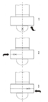
The figure below illustrates the tool motion during this cycle:
|
|
|
1. Z Minus |
|
|
2. X/Y Plus |
|
|
3. X/Y Minus |
|
|
|
|
|
|
Probe Deflection Offset Calibration
Tool and part probe deflection offsets are the difference between the contact point of the probe and the actual receipt of a probe deflection signal. The offsets may vary for each direction of deflection. The switch points are repeatable to one micron or less.
These offsets need to be adjusted during an initial probe installation, a new stylus installation, or for centering or re-centering a stylus. They do not need to be performed each time the control is reset.
Tool Probe Deflection Offset
Access the Tool Probe Deflection Offset screen from the Tool Setup screen. Select the Tool Probing softkey, the Tool Probe Setup softkey, and the Tool Probe Deflection Offset softkey. This screen appears:
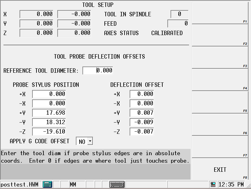
The Reference Tool Diameter field holds the diameter of the tool being probed.
The probe orientation determines the offsets used in the Probe Stylus Position fields. The -Z offset is always used along with +/-X or +/-Y, depending from which direction the probe can deflect.
The following sections describe the two methods for determining Tool Probe Deflection Offsets: Absolute Location or Reference Tool Touch.
Absolute Location
Use an edge finder to determine the absolute location of each edge of the probe stylus.
-
Enter the Reference Tool Diameter.
-
Position the cursor on the desired offset field.
-
Position the reference tool to the correct start position.
-
Press the Use Probe To Determine Offset softkey. The Start Button flashes.
-
Press the flashing Start Button.
-
The cursor position determines which axis is moved and in what direction.
-
The deflected position is used to calculate the offsets.
-
The offset value appears in the current field.
-
The offsets are saved by the system so they are retained after power to the machine is turned off.
-
Unused fields contain a 0 value.
-
The sign of the offset is + for plus axis deflections and - for negative axis deflections.
-
|
|
The Apply G Code Offset parameter applies the deflection offsets to G31 commands when conversational and NC probing are used together. |
Reference Tool Touch
Use a feeler gauge to determine the position where the reference tool touches the top and each side of the probe stylus. Follow the prompts on the screen to know which side of the stylus to use. Follow these steps:
-
Enter a 0 for the Reference Tool Diameter.
-
Position the reference tool in the correct start position. Begin with the top of the stylus.
-
Place the cursor in the -Z field of the Probe Stylus column.
-
Press the USE PROBE TO DETERMINE OFFSET (F1) softkey. The Start Button flashes.
-
Press the flashing Start Button.
-
The cursor position determines which axis is moved and in what direction.
-
The deflected position is used to calculate the offsets.
-
The offset value appears in the -Z field.
-
The offsets are saved by the system so they are retained after power to the machine is turned off.
-
Unused fields contain a 0 value.
-
The sign of the offset is + for plus axis deflections and - for negative axis deflections.
-
-
Repeat these steps for the other two axis positions (+/- X and +/-Y). Position the reference tool appropriately and put the cursor in the appropriate Probe Stylus field.
You can manually adjust the deflection offsets to optimize performance. By running a probe cycle on a reference tool you may make slight adjustments to the deflection offsets until the cycle returns with the exact value(s) desired.
|
|
The Apply G Code Offset parameter applies the deflection offsets to G31 commands when conversational and NC probing are used together. |