Automatic Tool Changers
The ATC for HMX, HTX, DCX, and VTXU machines is a random-pocket tool changer that tracks tools in the magazine using an ATC Map. All ATC operations require that the servo power is on, that the machine is calibrated, and that the ATC is at Home position.
Loading Tools into the ATC Magazine
The ATC takes a tool from the spindle and automatically loads it into the magazine, if space allows. The tool’s location in the magazine is recorded in the ATC Map (the Horizontal Chain Type ATC does not use an ATC Map). Before loading a tool into the ATC magazine, the Servo power must be On, and the machine must be calibrated.
|
|
Do not manually load tools directly into the magazine. |
To load the tool currently in the spindle into the ATC magazine:
-
Press the Manual Mode console key.
-
Select the Tool Management softkey. The Spindle tab displays the Tool in Spindle, Next Tool, and ATC Map (Swing-Arm Random Pocket ATC only) fields appear.
-
Verify that the Tool In Spindle value matches the tool currently in the spindle. If the numbers do not match, enter the correct tool number.
-
Enter the same tool number into the Next Tool field.
-
Press the Tool Changer Auto console key.
-
Enter a new tool number into the Next Tool field. The ATC Map field must be Auto.
-
Press the Tool Changer Auto console key. The Start Cycle light begins flashing.
-
Clear the tool changer and shut the enclosure door. Press the Start Cycle button. The Tool In Spindle field will be updated to the next tool value.
-
If the Next Tool is an Auto tool, it was placed into the magazine when the previous tool was removed from the spindle.
-
If the Next Tool is a Manual tool, you will be prompted to insert it into the spindle.
-
Removing Tools from the ATC Magazine
Remove tools from the ATC magazine by following these steps:
-
Press the Manual Mode console key.
-
Select the Tool Management softkey to display the Tool in Spindle. If there is no tool in the spindle, set the Tool In Spindle field to 0 (zero).
|
|
The ATC Map field will indicate if the tool selected is in the magazine, and its location. |
-
Enter the tool number (of the tool you want to remove in the magazine) into the Next Tool field.
-
Press the Tool Changer Auto console key to move the Next Tool into the spindle.
-
Clear the tool changer area and shut the enclosure door. Press the Start Cycle button to initiate the tool change.
-
Press the Spindle Unclamp button and manually remove the tool from the spindle.
-
Repeat steps 2 through 6, as needed, to remove additional tools from the ATC magazine.
Large Tools in the ATC Magazine
A part program may require tools with large diameters. These tools can be manually loaded by the operator, or automatically loaded.
|
|
The ATC magazine capacity is reduced by half for tools larger than 80 mm (125 mm for some machines). |
Follow these steps to load large tools into the ATC magazine:
-
Touch the ATC Map softkey from the Spindle screen. The ATC Map appears.
-
Touch the Max. Tool Dia. More than XX mm softkey.
-
An “ATC Map will be cleared! Are you sure you want to change Max. Tool Diameter to more than XX mm?” message appears.
|
|
Each time you switch between large and small tools, the entire ATC Map will be cleared and the magazine must be reloaded. |
-
Select the Yes softkey. The ATC Map will clear, then reappear. Only the odd numbered tool pockets will be available.
-
Reload tools into the magazine using the “Loading a Tool into the Spindle” section.
-
Return to the default setting of Maximum Tool Diameter XX mm or Less by using the previous procedure and touching the Max. Tool Dia. XX mm or Less softkey.
Each VMX or VM machining center is equipped with a swing-arm random pocket Automatic Tool Changer (ATC).
VM Tool Magazine
The station magazine is positioned vertically on the machine. An electronic motor and helical gear drive the magazine. When activated, the tool magazine operates as described below:
-
The requested tool pocket rotates 90° to make the tool available for the swing arm.
-
The swing arm rotates 60° to simultaneously grab the tool in the pocket and the tool in the spindle.
-
The spindle unclamps.
-
The swing arm moves down to pull the tools out of the pocket and the spindle, and then rotates 180°.
-
The swing arm moves up and swaps the tools.
-
Finally, the swing arm and tool pocket return to their original positions.
There are two types of ATCs, which are described in the following sections:
-
40-Taper ATC with 24- or 40-Station Tool Magazine
-
50-Taper ATC with 30- or 32-Station Tool Magazine
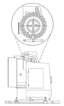
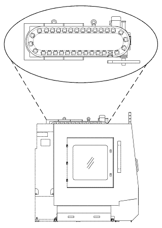
40-Taper ATC with 24- or 40-Station Tool Magazine
This tool changer features a magazine with either 24 or 40 tool pockets (stations). The magazine is positioned vertically on the machine. An electric motor and helical gear drive the 24- and 40-station magazine. The 24-station magazine is round and the 40-station magazine is elliptical. Refer to the previous table for the number of tool pockets (stations) available for a specific machining center.
ATC Sequence
This is the basic sequence of operation of the tool magazine, assuming the magazine is positioned to the next tool required:
-
The requested tool pocket rotates down 90° to make the tool available for the swing arm.
-
The swing arm rotates 60° to simultaneously grab both the tool in the pocket and the tool in the spindle.
-
The spindle unclamps.
-
The swing arm moves down to pull the tools out of the pocket and spindle, and then the arm rotates 180°.
-
The swing arm moves up and swaps the tools.
-
The spindle clamps the new tool in the spindle and the swing arm rotates back to 0°.
-
The tool pocket moves back to its original position.
50-Taper ATC with 30 or 32-Station Tool Magazine
The VMX50/50T uses the 50-Taper ATC with a 30-station tool magazine. The VMX64 uses the 50-Taper ATC with a 32-station tool magazine.
An electric motor, two dogs (cam detents), and three proximity switches control the 50-Taper tool changer motion. For the VMX64, a free-standing hydraulic unit runs the rotation of the magazine, magazine locking cylinder, and the tool pot up and down cylinder. The ATC sequence for the 50-taper ATC is the same as the 40-taper ATC sequence.
HMX and VTXU Tool Magazine
The ATC can be operated in Auto or Manual machine mode, using ATC Diagnostics.
HMX Machines
For HMX machines, the following steps explain the basic sequence of operation of the tool magazine, assuming the magazine is positioned to the next tool required.
-
The tool holder rotates to 90°, and the ATC door opens.
-
The exchange arm rotates to 90° and simultaneously grabs the tool in the tool holder, and if present, the tool in the spindle, if the following conditions are met:
-
The X, Y, and Z axes are at tool change position.
-
The spindle is oriented.
-
-
The spindle unclamps.
-
The exchange arm moves out and simultaneously pulls the tools from the holder and the spindle, then rotates 180°.
-
The exchange arm moves in and swaps the tools.
-
The exchange arm rotates to 90°.
-
The ATC door closes and the tool holder simultaneously returns to its original position.
VTXU Machines
The following steps describe the basic sequence of operation of the tool magazine in the VTXU magazine, assuming the magazine is positioned to the next tool required.
-
The ATC door opens if the following conditions are met:
-
The X and Y axes are at tool change position.
-
The Z axis is at Height (refer to ATC and Machine Diagnostics for more information).
-
The spindle is oriented.
-
-
The tool pocket rotates from the Up position to the Down position.
-
The swing arm rotates 90° and simultaneously grabs the tool in the tool pocket and, if present, the tool in the spindle.
-
The spindle unclamps.
-
The swing arm moves up and swaps the tools, then rotates 180°.
-
The swing arm and tool pocket return to the original positions.
-
The ATC door closes.
ATC Diagnostics and Machine Diagnostics
ATC Diagnostics and Machine Diagnostics display status and diagnostics information. Follow these steps to display the ATC Diagnostics or Machine Diagnostics screen:
-
Press the Machine Mode Manual console key.
-
Select the Diagnostics softkey.
-
Select the Machine Diagnostics or ATC Diagnostics softkey.
ATC and Machine Diagnostics Fields
See the Field Glossary for definitions of the fields on the ATC and Diagnostic screens. Note not all fields listed here are displayed for every machine model and configuration:
|
|
|||
|
|
|||
|
|
|||
|
|
|||
|
|
ATC Diagnostics and Machine Diagnostics Softkeys
When all requirements for a softkey action are met, a prompt displays and the Start Cycle lamp flashes. Pressing the Start Cycle button executes the command. The Start Cycle lamp stops flashing during the execution of the command and is turned off when the command is completed.
Selecting another softkey before pressing the Start Cycle button cancels the pending command and causes the Start Cycle lamp to cease flashing. If the requirements for a softkey action are not met, a message displays indicating why the action cannot be commanded. The ATC & Machine Diagnostics softkeys are listed below; some softkeys may not be present on all machines or may appear in a different order:
-
Orient Spindle—sets the command to orient the spindle. Oriented is required to begin an ATC cycle.
-
ATC Door Open/Close—sets the command to open or close the ATC Door. Each press of the softkey switches command between open and close. Must be Closed for ATC to begin.
-
Tool Holder 0º/90º—sets the command to move the Tool Holder to 0° or 90°. Each press of the softkey switches command between 0° and 90°.
-
Tool Holder Up / Down—sets the command to move the Tool Holder Down or Up. Each press of the softkey switches command between Down and Up.
-
Exchange Arm 0º / 60º / 90º—sets the command to move the Exchange Arm to 0° or 60°/90°. For VM, VMX, VTXU machines, Tool Pocket must be Z-axis at Tool Change Height, Spindle Clamped, and Oriented Down before moving to 60° (90°). For HMX machines, Tool Holder must be at 90°, and ATC Door Open; once rotated to 90°, the Exchange Arm must be rotated to 180° or jogged back to 0°.
-
Spindle Clamp/Unclamp—sets the command to clamp or unclamp the spindle. Each press of the softkey switches the command between clamp and unclamp.
-
Exchange Arm 180º—sets the command to move the Exchange Arm out, rotate 180° and in. Tool Holder must be at 90º and ATC Door Open. Must be at 0º for ATC to begin.
-
Exchange Arm Rotate—sets the command to move the Exchange Arm down, rotate 180° and up. Tool Pocket must be Down, Load Arm must be at 60°, and spindle must be unclamped.
-
Exchange Arm Jog Reverse—sets the command to pulse jog the exchange arm in the reverse direction. Pulse commands will stop once the Exchange Arm is at 0 degrees.
-
Move Axes to TC Position—sets the command to move all required axes to the ATC position.
-
Move Z-Axis to Zero—sets the command to move the Z-axis to the Zero position.
-
Magazine Pin Lock / Unlock—sets the command to lock or unlock the magazine pin. Locked is required for ATC to begin.
-
Magazine CW—sets the command to move the magazine clockwise one position.
-
Magazine CCW—sets the command to move the magazine counter-clockwise one position.
-
Calibrate T/C Magazine—sets the command to calibrate the magazine. The magazine will rotate to the Reference Pos.