Tool Calibration Modes
Tool measurement and Part Setup Z measurements can be set with one of two modes: Zero Calibration or Absolute Tool Length. The mode is selected in Utilities/User Preferences/Part and Tool Settings. See Part and Tool Settings.
|
|
If a program’s tools were calibrated using one mode, and that program is loaded into a control that is set to the other mode, a message is displayed that the program’s tool calibrations cannot be used. The program data is loaded, but the tool calibration data is not; tool calibration fields are set to zero. |
Absolute Tool Length mode
With the Absolute Tool Length method, the absolute length of the tool from the spindle nose to the tip of the tool is stored in Tool Setup. Each tool used in a program should be calibrated to the same gauge device set on table top. To use Absolute Tool Length Mode:
-
In the Tool Setup screen, enter the number of the tool to be calibrated into the Tool Number field.
-
If the tool is in spindle, jog Z down to the gauge block.
-
Select Store Machine Position softkey or button on the Jog Unit.
-
Part Zero is stored separately in the Part Zero Z field in Part Setup and is the distance from Machine Zero to the Z0 of the workpiece:
-
Select Part Setup softkey.
-
In Part Zero Z field, use calibrated tool to touch off Z0 of the workpiece and select the Store Machine Position softkey or button on the jog unit.
-
Setup of Gauge Device
To use Absolute Tool Length mode, you must define the Z location for the table top and the touch off device(s). This needs to be done only once unless the touch off device changes. Access the Tool Measurement screen with the Tool Measurement Settings softkey on the 2nd set of Tool Setup softkeys (use the More softkey):
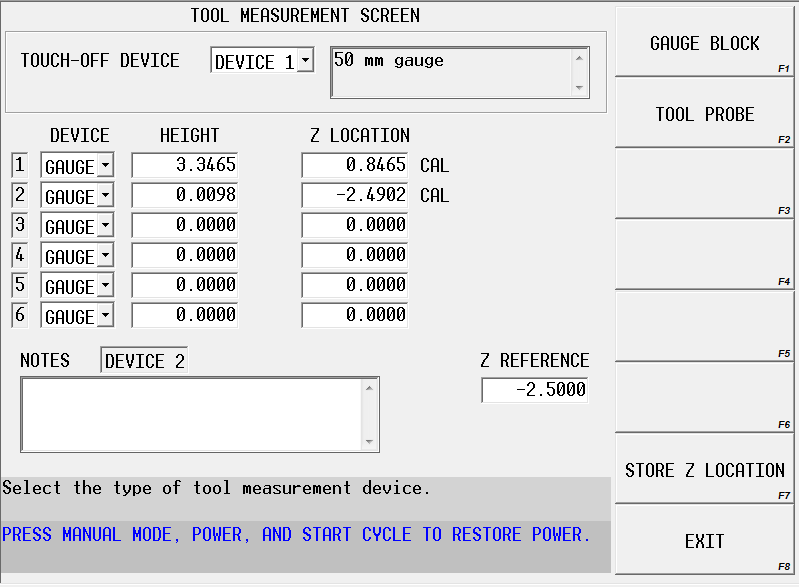
See the Field Glossary for definitions of the Tool Measurement fields:
To set the Z Reference position
-
Advance to Z Reference field.
-
Place a gauge of known length on table top.
-
Jog Z-axis down and carefully touch spindle nose to top of gauge block.
-
Select Store Machine Position softkey or press the store position button on remote jog unit.
|
|
The Part Kinematics Z Reference value from Rotary Axes Parameters may also be used as the Z Reference value by selecting the Set to Part Kinematics Ref softkey. |
-
Subtract the length of the gauge block from the value stored in Z Reference field.
|
|
With Z Reference field highlighted, you can type in length of the gauge block followed by enter. For example, if Z Reference measures |
|
|
Once Z Reference is set it does not have to be changed or set again, even if new devices are used. This field and the calculated Z Location fields should not be edited. |
To set up a gauge device
-
In the Touch-Off Device field, select the device number to be used when measuring tool length. Up to six different devices can be set, but only the one currently selected in the Touch-Off Device field is active when setting tool length.
-
Advance to the row number that corresponds to the touch-off device number.
-
In the Device column, select gauge.
-
In the Height column, enter the height of the gauge.
|
|
Z Location field will be automatically calculated by adding the height to the Z Reference value. Do not edit Z Location column. |
-
Multiple gauges can be set up by specifying height in the appropriate row (1-6). However, the active device for measuring tool length is the one specified in the Touch-Off Device field.
|
|
All values set in Tool Measurement Settings are retained in the control and are applicable to all programs. They are not program specific. |
To set up a probe device
-
Follow the steps to set up a single gauge device (for example, set up gauge for device) and set touch-off device to Device 1.
-
In Tool Setup, use any tool to touch-off on the Device 1 gauge.
-
Select Store Machine Position softkey or Store Position button on jog unit.
-
In Tool Measurement Screen, select the touch-off device to be used when probing tool length.
-
In the appropriate row, select Probe as the device from the drop-down Device list.
-
Jog the tool down to the probe until probe is engaged.
-
With cursor in the Z Location column, select Store Position button on jog unit or Store Z Location softkey. This will calculate the height of the probe from Z Reference.
Also see Tool Probing in Options for more information.
Zero Calibration Mode
With the Zero Calibration method of tool measurement, tools are calibrated to a plane in the Z-axis as referenced from the Z Home position. Each tool used in a program should be calibrated to the same plane. To use Zero Calibration mode:
-
In the Tool Setup screen, enter the number of the tool to be calibrated into the Tool Number field.
-
If the tool is in spindle, jog Z down to the reference plane or gauge block.
-
Select Store Machine Position softkey or button on the Jog Unit.
|
|
All tools should be calibrated to the same reference plane. |
-
If the reference plane is not the same as Z=Part Zero for program depth:
-
Select Part Setup softkey.
-
In Offset Z field, enter distance from reference plane to Part Zero, or use calibrated tool to touch off Z=0 plane and select the Store Machine Position softkey or button on the Remote Jog Unit.
-
If the plane that all tools are touched off of is the top of the workpiece, all program dimensions for Z will be from Z=0. If the plane is not the top of the workpiece (as when a gauge block is used), the operator can use the Offset Z field in Part Setup to set the distance from the gauge block or other plane to the top of the workpiece plane. See Part Setup for more information.