G Code Table
The following table lists the G codes, identifies the defaults (in the shaded areas), lists Modal (M) or Non-modal (N) types, identifies groups, and describes the G codes’ functions.
Some G codes are strictly BNC or strictly ISNC, and are identified as such in this manual. Otherwise, the G codes apply to either dialect.
|
G Code |
Type |
Group |
Function |
|---|---|---|---|
|
G00 |
M |
01 |
Positioning (Rapid Traverse) |
|
G01 |
M |
|
Linear Interpolation (Cutting Feed) |
|
G02 |
M |
|
Circular Interpolation/Helical CW |
|
G02.4 |
M |
|
3D Circular Interpolation CW |
|
G03 |
M |
|
Circular Interpolation/Helical CCW |
|
G03.4 |
M |
|
3D Circular Interpolation CCW |
|
G04 |
N |
00 |
Dwell, Exact Stop |
|
G05.1 |
M |
19 |
Surface Finish Parameters |
|
G05.2 |
M |
Data Smoothing |
|
|
G05.3 |
M |
Surface Finish Quality |
|
|
G07.2 |
M |
00 |
Cylindrical Rotary Wrap On |
|
G07.3 |
M |
00 |
Cylindrical Rotary Wrap Off |
|
G08.1 |
M |
00 |
ASR Command Buffer On |
|
G08.2 |
M |
00 |
ASR Command Buffer Off |
|
G09 |
N |
00 |
Exact Stop |
|
G10 |
N |
|
Data Setting |
|
G11 |
N |
|
Data Setting Mode Cancel |
|
G15 |
M |
17 |
Polar Coordinates Cancel |
|
G16 |
M |
|
Polar Coordinates |
|
G17 |
M |
02 |
XY Plane Selection |
|
G18 |
M |
|
ZX Plane Selection |
|
G19 |
M |
|
YZ Plane Selection |
|
ISNC G20 |
M |
06 |
Input in Inch |
|
ISNC G21 |
M |
|
Input in mm |
|
G28 |
N |
00 |
Return to Reference Point |
|
G29 |
N |
|
Return from Reference Point |
|
G31 |
N |
|
Skip Function |
|
G Code |
Type |
Group |
Function (Continued) |
|---|---|---|---|
|
G40 |
M |
07 |
Cutter Compensation Cancel |
|
G41 |
M |
|
Cutter Compensation Left |
|
G41.2 |
M |
|
3D Tool Geometry Compensation |
|
G42 |
M |
|
Cutter Compensation Right |
|
G43 |
M |
08 |
Tool Length Compensation + Direction |
|
G43.4 |
M |
|
5-Axis Linear Interpolation |
|
G44 |
M |
|
Tool Length Compensation - Direction |
|
G45 |
N |
00 |
Tool Offset Increase |
|
G46 |
N |
|
Tool Offset Decrease |
|
G47 |
N |
|
Tool Offset Double Increase |
|
G48 |
N |
|
Tool Offset Double Decrease |
|
G49 |
M |
08 |
Tool Length Offset Compensation Cancel |
|
G50 |
M |
11 |
Scaling Cancel |
|
G51 |
M |
|
Scaling |
|
G50.1 |
M |
18 |
Mirroring Cancel |
|
G51.1 |
M |
|
Mirroring |
|
G52 |
N |
00 |
Local Coordinate System Setting |
|
G53 |
N |
|
Machine Coordinate System Selection |
|
G54 |
M |
14 |
Work Coordinate System 1 Selection |
|
G54.1 |
M |
|
Aux Work Coordinate Systems |
|
G55 |
M |
|
Work Coordinate System 2 Selection |
|
G56 |
M |
|
Work Coordinate System 3 Selection |
|
G57 |
M |
|
Work Coordinate System 4 Selection |
|
G58 |
M |
|
Work Coordinate System 5 Selection |
|
G59 |
M |
|
Work Coordinate System 6 Selection |
|
G61 |
M |
15 |
Decelerates to Zero–Precision Cornering |
|
G64 |
M |
|
Cancels Precision Cornering |
|
G65 |
N |
12 |
Macro Command, Subprogram Call |
|
G66 |
M |
|
Modal Subprogram Call |
|
G67 |
M |
|
Modal Subprogram Call Cancel |
|
G68 |
M |
16 |
Coordinate Rotation |
|
G68.2 |
M |
|
Global Rotation NC Transform Plane |
|
G68.3 |
M |
|
Local Rotation NC Transform Plane |
|
G69 |
M |
|
Coordinate System Rotation Cancel |
|
G69.1 |
M |
|
Cancel All Active Transform Planes |
|
BNC G70 |
M |
06 |
Input in Inch |
|
BNC G71 |
M |
|
Input in mm |
|
G73 |
M |
09 |
Peck Drilling Cycle |
|
ISNC G74 |
M |
|
Left-handed Tapping Cycle |
|
ISNC G74 |
M |
|
Left-handed Rigid Tapping |
|
BNC G74 |
M |
01 |
Single-quadrant Circular Interpolation |
|
BNC G75 |
M |
|
Multi-quadrant Circular Interpolation |
|
G76 |
M |
09 |
Bore Orient Cycle |
|
G80 |
M |
|
Canned Cycle Cancel |
|
G81 |
M |
|
Drilling Cycle, Spot Boring |
|
G82 |
M |
|
Drilling Cycle, Counter Boring |
|
G83 |
M |
|
Peck Drilling Cycle |
|
G84 |
M |
|
Tapping Cycle |
|
ISNC G84.2 |
M |
|
Rigid Tapping Cycle |
|
ISNC G84.3 |
M |
|
Rigid Tapping Cycle |
|
ISNC G84 with M29 |
M |
|
Rigid Tapping Cycle |
|
G85 |
M |
|
Boring Cycle |
|
BNC G86 |
M |
|
Bore Orient Cycle |
|
ISNC G86 |
M |
|
Bore Rapid Out Cycle |
|
BNC G87 |
M |
|
Chip Breaker Cycle |
|
ISNC G87 |
M |
|
Back Boring Cycle |
|
BNC G88 |
M |
|
Rigid Tapping Cycle |
|
G89 |
M |
|
Boring Cycle Bore and Dwell |
|
G90 |
M |
03 |
Absolute Command |
|
G91 |
M |
|
Incremental Command |
|
G92 |
N |
00 |
Programming of Absolute Zero Point |
|
G93 |
M |
05 |
Inverse Time |
|
G94 |
M |
|
Feed per Minute |
|
G94.1 |
M |
05 |
Rotary Tangential Velocity Control |
|
G95 |
M |
|
Feed per Revolution |
|
G98 |
M |
10 |
Return to Initial Point in Canned Cycle |
|
G99 |
M |
|
Return to R Point in Canned Cycle |
|
Table 3–2.G Codes in order of Codes |
|||
The following table lists the G codes by group, identifies the defaults (shaded areas), lists Modal (M) or Non-modal (N) types, and describes the G codes’ functions.
|
Group |
G Codes |
Type |
Function |
|---|---|---|---|
|
00 |
G04 |
N |
Dwell, Exact Stop |
|
G07 |
M |
Cylindrical Rotary Wrap |
|
|
G08 |
M |
ASR Command Buffering |
|
|
G09 |
N |
Decelerate Axis to Zero |
|
|
G10 |
N |
Data Setting |
|
|
G11 |
N |
Data Setting Mode Cancel |
|
|
G28 |
N |
Return to Reference Point |
|
|
G29 |
N |
Return from Reference Point |
|
|
G31 |
N |
Skip Function |
|
|
G45 |
N |
Tool Offset Increase |
|
|
G46 |
N |
Tool Offset Decrease |
|
|
G47 |
N |
Tool Offset Double Increase |
|
|
G48 |
N |
Tool Offset Double Decrease |
|
|
G92 |
N |
Programming of Absolute Zero Point |
|
|
01 |
G00 |
M |
Positioning (Rapid Traverse) |
|
G01 |
M |
Linear Interpolation (Cutting Speed) |
|
|
G02 |
M |
Circular Interpolation/Helical CW |
|
|
G02.4 |
M |
3D Circular Interpolation CW |
|
|
G03 |
M |
Circular Interpolation/Helical CCW |
|
|
G03.4 |
M |
3D Circular Interpolation/Helical CCW |
|
|
BNC G74 |
M |
Single-quadrant Circular Interpolation |
|
|
BNC G75 |
M |
Multi-quadrant Circular Interpolation |
|
|
02 |
G17 |
M |
XY Plane Selection |
|
G18 |
M |
ZX Plane Selection |
|
|
G19 |
M |
YZ Plane Selection |
|
Group |
G Codes |
Type |
Function (Continued) |
|---|---|---|---|
|
03 |
G90 |
M |
Absolute Command |
|
G91 |
M |
Incremental Command |
|
|
05 |
G93 |
M |
Inverse Time |
|
|
G94 |
M |
Feed per Minute |
|
|
G94.1 |
M |
Rotary Tangential Velocity Control |
|
|
G95 |
M |
Feed per Revolution |
|
06 |
BNC G70 |
M |
Input in Inch |
|
BNC G71 |
M |
Input in mm |
|
|
07 |
G40 |
M |
Cutter Compensation Cancel |
|
G41 |
M |
Cutter Compensation Left |
|
|
G41.2 |
M |
3D Tool Geometry Compensation |
|
|
|
G42 |
M |
Cutter Compensation Right |
|
08 |
G43 |
M |
Total Length Compensation + Direction |
|
G43.4 |
M |
5-Axis Linear Interpolation |
|
|
G44 |
M |
Total Length Compensation – Direction |
|
|
G49 |
M |
Tool Length Offset Compensation Cancel |
|
09 |
G73 |
M |
Peck Drilling Cycle |
|
ISNC G74 |
M |
Left-handed Tapping Cycle |
|
|
ISNC G74 with M29 |
M |
Rapid Tapping |
|
|
G76 |
M |
Bore Orient Cycle |
|
|
G80 |
M |
Canned Cycle Cancel |
|
|
G81 |
M |
Drilling Cycle, Spot Boring |
|
|
G82 |
M |
Drilling Cycle, Counter Boring |
|
|
G83 |
M |
Peck Drilling Cycle |
|
|
G84 |
M |
Tapping Cycle |
|
|
ISNC G84.2 |
M |
Rigid Tapping Cycle |
|
|
ISNC G84.3 |
M |
Rigid Tapping Cycle |
|
|
ISNC G84 with M29 |
M |
Rigid Tapping Cycle |
|
|
G85 |
M |
Boring Cycle |
|
|
BNC G86 |
M |
Bore Orient Cycle |
|
|
ISNC G86 |
M |
Bore Rapid Out Cycle |
|
|
BNC G87 |
M |
Chip Breaker Cycle |
|
|
ISNC G87 |
M |
Back Boring Cycle |
|
|
BNC G88 |
M |
Rigid Tapping Cycle |
|
|
G89 |
M |
Boring Cycle, Bore and Dwell |
|
Group |
G Codes |
Type |
Function (Continued) |
|---|---|---|---|
|
10 |
G98 |
M |
Return to Initial Point in Canned Cycle |
|
G99 |
M |
Return to R Point in Canned Cycle |
|
|
11 |
G50 |
M |
Scaling Cancel |
|
G51 |
M |
Scaling |
|
|
12 |
G65 |
N |
Macro Command, Subprogram Call |
|
G66 |
M |
Modal Subprogram Call |
|
|
G67 |
M |
Modal Subprogram Call Cancel |
|
|
14 |
G54 |
M |
Work Coordinate System 1 Selection |
|
G55 |
M |
Work Coordinate System 2 Selection |
|
|
G56 |
M |
Work Coordinate System 3 Selection |
|
|
G57 |
M |
Work Coordinate System 41 Selection |
|
|
G58 |
M |
Work Coordinate System 5 Selection |
|
|
G59 |
M |
Work Coordinate System 6 Selection |
|
|
15 |
G61 |
M |
Decelerates to Zero-Precision Cornering |
|
G64 |
M |
Cancels Precision Cornering |
|
|
16 |
G68 |
M |
Coordinate Rotation |
|
G68.2 |
M |
Global Rotation NC Transform Plane |
|
|
G68.3 |
M |
Global Rotation NC Transform Plane |
|
|
G69 |
M |
Coordinate System Rotation Cancel |
|
|
17 |
G15 |
M |
Polar Coordinate Cancel |
|
G16 |
M |
Polar Coordinates |
|
|
19 |
G05.1 |
M |
Surface Finish Parameters |
|
G05.2 |
M |
Data Smoothing |
|
|
G05.3 |
M |
Surface Finish Quality |
G Codes in order of Groups
Rapid Traverse (G00)
Rapid Traverse mode (G00) is the default and moves the axes to a specified location at the rapid feedrate programmed in the Program Parameters screen. Up to five axes (X, Y, Z, A, B, C) of coordinated rapid motion can be specified while in this mode.
Set either a linear or non-linear tool path on the NC Parameters screen. The linear tool path is the default. ISNC and BNC have different linear tool path modes. In the ISNC linear mode the tool motion is in all three axes (X, Y, Z) simultaneously. In the BNC linear mode the motion is divided into separate X, Y, and Z moves. The motion in the XY plane is a straight line.
The ISNC and BNC non-linear modes are the same. In the non-linear tool path mode, the XY plane motion is broken down into a 45° move and a straight line move parallel to either the X or Y axis. The determination of whether the 45° move or the straight line move is made depends first on the distances from the current position to the end position along the X and Y axes.
If it is desired that the tool move to a position which is compensated, G41 or G42 needs to be specified along with the offset before any axis coordinates are given. The rapid traverse rate is set on the General Parameters screen.
|
|
The G00 mode is canceled by using the G01, G02, G03, or canned cycle (G73, G76, G81–G89) commands. G17, G18, or G19 determine plane of offset. G90 specifies absolute dimensioning and G91 specifies incremental dimensioning. Another work coordinate system can be selected by using commands G54 through G59. |

Format
The format of the rapid traverse command is as follows:
G00 X_____Y_____Z_____A_____B_____C____W____
where
X is the Primary X Motion Dimension
Y is the Primary Y Motion Dimension
Z is the Primary Z Motion Dimension
A is the Rotary Dimension around X-axis
B is the Rotary Dimension around Y-axis
C is the Rotary Dimension around Z-axis
W is the secondary, linear axis in the Z direction
Example
If one axis of movement is specified in a G00 block, that axis moves at the rapid traverse feedrate. When two axes of movement are specified in a G00 block, the rapid traverse feedrate is assigned to the longest vector component. The resulting feed that appears on the screen may actually exceed the rapid traverse feedrate parameter.
If a block containing a G00 word also contains a Z word that causes the Z-axis to move away from the part, the Z-axis moves first. The other specified axes then move in linear or non-linear mode at the rapid feedrate to their specified end points. If Z is to move toward the part, all axes except Z move in linear or non-linear mode at rapid feedrate to their specified end points; then Z moves down to its end point. If no Z is programmed, all axes move at rapid feedrate coordinated to the specified end point. G00 is a member of the tool positioning code group and is canceled by G01, G02, G03, and G81–G89.
|
|
This code is used for positioning only and should never be used for cutting material. |
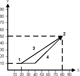
The diagram below shows the two different rapid traverse modes:
|
1 |
Start Point |
|
2 |
End Point |
|
3 |
Linear |
|
4 |
Non-Linear |
Linear Interpolation (G01)
The Linear Interpolation code (G01) moves the axes to a specified location at the programmed feedrate. Up to five axes (X, Y, Z, A, B, C) of coordinated motion can be specified while in this mode. The programmed feedrate can be changed by adding an F word to any NC block while in this mode. X, Y, Z, A, B, C, and F dimensions need to be supplied only if they change.
|
|
G01 is a member of the tool positioning code group and is canceled by G00, G02, G03 and the canned cycle (G73, G76, G81–G89) commands. G90 specifies absolute dimensioning and G91 specifies incremental dimensioning. G41 or G42 may be optionally selected if a cutter offset is desired. |

|
|
This code is used when the tool is in contact with the work piece to cut a line parallel to an axis or at an angle to an axis. |

Format
The format of the linear interpolation command is as follows:
G01 X_____ Y_____ Z_____ A_____ B_____C____ F_____
where
X is the Primary X Motion Dimension
Y is the Primary Y Motion Dimension
Z is the Primary Z Motion Dimension
A is the Rotary Dimension around X-axis
B is the Rotary Dimension around Y-axis
C is the Rotary Dimension around Z-axis
F is the Feedrate. If rotary axis parameters (A and B) are used, the feedrate units are in degrees/minute.
Example
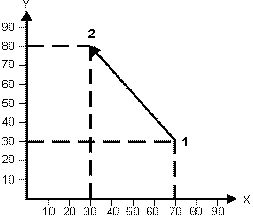
The diagram below illustrates the linear interpolation axis movement:
|
1 |
Start Point |
|
2 |
End Point |
Circular and Helical Interpolation (G02 and G03)
These two codes are members of the tool positioning code group. The Clockwise Circular or Helical Interpolation code (G02) causes the axes to generate an arc or helix in a clockwise direction. The previous block’s end point defines the start point of the arc.
|
|
If the first segment in a contour is an arc with a radius smaller than the radius of the tool, the +-control will generate an error message indicating that you need to use a tool with a smaller radius or program a larger radius. An error message is generated only if the Enable Lead In/Out Error Checking parameter in NC Configuration Parameters is Yes. |

The Counterclockwise Circular or Helical Interpolation code (G03) causes the axes to generate an arc or helix in a counterclockwise direction. The previous block’s end point defines the start point of the arc.
|
|
Calculate the linear feedrate to verify that it does not exceed various limit values. |

|
|
Both G02 and G03 codes are canceled by G00, G01, the canned cycle (G73, G76, G81–G89) commands, or by each other. The programmed feedrate can be changed by adding an F word to any NC block when this code is active. G17, G18, or G19 specify plane of interpolation. G41 or G42 may be optionally selected if a cutter offset is desired. G40 is used to cancel cutter offset. G02 or G03 cannot be used in a start up block in offset mode. (X,Y) for G17, (X,Z) for G18, and (Y,Z) for G19 specify the end location on the selected plane. R or the incremental coordinates ((I,J) or (I,K) or (J,K)) specify the arc center location. The R is modal and stays in effect until another R value is specified or (I,J) is used. With the R (radius) parameter, you specify the radius. You do not need to calculate the center point.
For BNC, I, J, K, and R are modal for G02 and G03. The I, J, and K center point location is incremental from start point in G91 mode and absolute coordinates in G90 mode. For ISNC, when G02 or G03 are specified, the I, J, and K are reset to 0.0. They remain modal until another G02 or G03 is encountered. R is not reset to 0.0. For ISNC, the I, J, and K are incremental from the start point in both G90 and G91 mode. |

|
|
You can specify an R value for arcs when the arc is in the G17 XY plane or the G19 YZ plane. If I, J, and K are not specified, the start and end points are the same, and only R is used to specify the center point, an arc of 0° is programmed. If cutter compensation is enabled, an invalid arc error appears because a center point cannot be calculated. Arcs use the right-hand coordinate system for all planes, except when using Basic NC for the G18 XZ plane. Arcs use a left-hand coordinate system when using the Basic NC for the G18 XZ plane. When interpreting an arc in ISNC, a helix will be the result if a valid center point was established in the previous block and only a Z value is given. F specifies the feedrate in degrees/minute along the arc in the circular plane. |

Format
The formats of the Circular Interpolation commands are as follows:
Circular interpolation (Z = 0)
Helical interpolation (Z ¹ 0)
G02/G03 (for G17) X_____ Y_____ {R_____ or [I_____ and J_____ ]}Z_____ F_____
G02/G03 (for G18) X_____ Z_____ {R_____ or [I_____ and K_____ ]}Z_____ F_____
G02/G03 (for G19) Y_____ Z_____ {R_____ or [J_____ and K_____ ]}Z_____ F_____
where
X is the Primary X Motion Dimension
Y is the Primary Y Motion Dimension
Z is the Primary Z Motion Dimension
R is the Circular Interpolation Radius
I is the X-axis Arc Center
J is the Y-axis Arc Center
K is the Z-axis Arc Center
F is the Feedrate
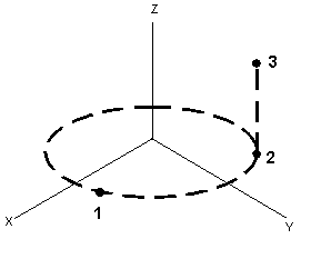
This diagram illustrates circular and helical interpolation:
|
1 |
Start Point |
|
2 |
End Point (Circular) |
|
3 |
End Point (Helical) |
G02 Example
Consider the following section of an NC program using a G02 code in absolute mode using R to specify the modal turn radius:
NC Part Program 1 Inch
G02.FNC
%
G00 G90
M25
T1 M06
Z5.05
X2.0 Y0.0
S2000 M03
Z0.05
G01 Z-0.5 F10.
G01 X2.0 Y0.0
G01 X0.5
G02 X0.0 Y0.5 R0.5 Ü R needs to be specified only once.
G01 Y2.5
G02 X0.5 Y3.0
G01 X3.5
G02 X4.0 Y2.5
G01 Y0.5
G02 X3.5 Y0.0
G01 X2.0
M25
M05
M02
BNC G03 Example
Consider the following section of a BNC program using a G03 code in absolute mode:
NC Part Program 1 Inch
G03ABS.HNC
%
N110 Z0 G91
N115 T01 M06
N116 X0. Y0. Z0.
N120 F40 S1000 M3
N130 G00 X3. Y4.
N140 G01 X3. Y2. F10
N150 G03 X4. Y1.5858 I4. J3.
N160 X7.4142 Y5. J5.
N170 G01 Y7.
N220 M02
E
This is an example of the same geometry using the incremental mode:
NC Part Program 1 Inch
G03INC.HNC
%
N110 Z0
N115 T01 M06
N116 X0. Y0. Z0.
N120 F40 S1000 M3
N130 G00 X3. Y4.
N140 G01 Y-2. F10
N150 G03 X1. Y-.4142 I1. J1.
N160 X3.4142 Y3. I0. J3.4142
N170 G01 Y2.
N220 M02
E
A, B, and C words are not allowed in circular interpolation mode. The programmed feedrate can be changed by adding an F word to any block while in this mode.
X, Y, and Z define the end point of the arc and I, J, and K define the center point of the arc. I represents the X center point; J represents the Y center point; and K represents the Z center point. The X, Y, Z, and F words do not need to be programmed when you are initially setting the circular interpolation mode if they have not changed from the previous block.
For BNC, the I, J, and K dimensions must be specified when initially setting the circular interpolation mode (when a G02 or G03 is in the block) to establish a center point.
For ISNC, I, J, or K are set to 0.0 if they are not initially specified.
Once the circular interpolation mode is set, the X, Y, Z, I, J, K, and F dimensions need to be supplied only if they change. A block with missing dimensions uses the last specified locations.
|
|
A circle or circular helix may be programmed by either using the same end and start point, or by not programming the end points. Ensure that the specified end point is mathematically on the arc. |

If the programmed end point is not on the arc or helix, an end point is calculated using the start point, center point, and programmed end point. The start point and center point determine the radius of the arc and thus the distance of the calculated end point from the center point. The center point and programmed end point determine the line on which the calculated end point results.
|
|
Arcs in this system are approximations that are comprised of small line segments or arc chords. |

The chord error of arcs and helices may be controlled through the chord error parameter in the Program Parameters screen. The default chord error is 0.0001 inches (.003 mm). This creates very smooth arcs, but may limit the maximum feedrate for the arc or helix. Larger chord errors allow higher feedrate arcs or helices, but may be less accurate.
3D Circular Interpolation (G02.4 and G03.4)
The 3D Circular Interpolation (G02.4 and G03.4) codes are part of the tool positioning code group. These codes require two lines of NC code:
-
The first line contains a set of X, Y, and Z values which represent the Intermediate Point.
-
The second line contains a set of X, Y, and Z values which represent the End Point.
The Radius, Direction (CW or CCW), and Center Point are calculated based on the current location, the Intermediate Point, and the End Point. G02.4 and G03.4 can be used interchangeably to represent the same arc. The actual direction is calculated by the software.
|
|
Both G02.4 and G03.4 codes are canceled by G00, G01, the canned cycle commands (G73, G76, G81-G89), or by each other. The programmed feedrate can be changed by adding an F word to any NC block when this code is active. G17, G18, G19 are irrelevant for these G codes. G41 and G42 may not be used with these G codes. |

Example
Below is a program example using G03.4:
%
T1 M6 S500 M3
G0 X0 Y0 Z6
G1 X0 Y0.0 F5.
Z0
G3.4 X5.0 Y2.5 Z1.0 (Intermediate Point)
X10.0 Y0.0 Z0.0 (End Point)
G0Z6
M2
E
Dwell Mode (G04)
The Dwell Mode code (G04) causes the machine to delay the shift to the next block in the program by the amount specified by parameter P or X for a specified amount of time. When an integer is used with the G04 command, the value is multiplied by 0.01 for BNC and.001 or .0001 for ISNC depending on the Least Dwell Units programmed on the NC Parameters screen.
The BNC format for the dwell time is as follows:
Real Number: .3 second = G04 X.3 or G04 P.3
Integer Number: .3 second = G04 X30 or G04 P30
This is the ISNC format for the dwell time programmed with a real number:
Real Number: .3 second = G04 X.3 or G04 P.3
When .001 is programmed for the Least Dwell Units field on the NC Parameters screen, the ISNC format for the dwell time programmed with an integer is this:
Integer Number: .3 second = G04 X300 or G04 P300
When .0001 is programmed for the Least Dwell Units field on the NC Parameters screen, the ISNC format for the dwell time programmed with an integer is this:
Integer Number: .3 second = G04 X3000 or G04 P3000
The Dwell Mode code is only active in the programmed block, but the dwell time is modal and it affects most of the canned cycles.
|
|
A decimal after an integer indicates whole seconds. For example, G04 P5 = .005 second dwell, while G04 P5. = 5 second dwell. |

Format
G04 P_____ or X_____
where
P is the Dwell Time
X is the Dwell Time
The range of values is 0.001–9999.999 seconds.
Surface Finish (G05.1)
Surface Finish G05.1 is obsolete, except for the Q parameter to establish the chord error. Use Surface Finish Quality (G05.3) to program the surface finish.
The code determines the type of finish quality, P_.
-
P1 = Precision
-
P2 = Standard
-
P3 = Performance
The parameter Q_ sets the chord segment for the finish, where the Q value is the acceptable error value.
Data Smoothing (G05.2)
Q_ sets the Tool Path Tolerance. The deviation from the tool path the system will tolerate must be between 0 to 0.0005 inches, inclusive (0 to 0.012 mm).
Surface Finish Quality (G05.3)
The G05.3 command is used with the Select Surface option.
G05.3 P_, where the P value is 1.0 to 100.0. P1 gives a smoother surface but requires a longer cutting time. P100.0 cuts down time to cut the part, but gives a rougher surface finish.
Cylindrical Rotary Wrap On (G07.2)
The G07.2 code wraps X-, Y-, and Z-axis commanded motion to a cylinder for 4- and 5-axis machines, and can be used in transform planes.
There are two methods for setting the cylinder location and orientation: Rotary Axis Method and Vector Method. Using default parameters for both styles, the X-direction is wrapped around the cylinder, the Y-direction points along the cylinder axis, and the Z-direction always maps to the cylinder radius.
Tool changes can be safely performed while milling with G07.2, because the control utilizes ASR Command Buffering. See Automatic Safe Repositioning Command Buffer On (G08.1).
Format
G07.2 requires parameters to identify the location and the orientation of the cylinder:
Rotary Axis Method
The Rotary Axis Method wraps XYZ to the cylinder.
G07.2 X_____Y_____Z_____ A_____P_____L_____Q_____
-
X_____Y_____Z_____ is cylinder coordinate system location with respect to the current coordinate system. If not specified, the control sets them to zero.
-
A______, B______ or C______ indicates cylinder axis is along X, Y or Z axis and the # indicates the mapping radius. Only one of these arguments is allowed. The radius cannot be zero. If the radius is negative, it will wrap to the inside of the cylinder along the negative radial direction (180 degrees rotation). A_, B_ or C_ can be specified to define the rotary axis to which the cylinder is parallel.
-
P_____ (optional) Indicates lead/lag distance (tangential to positive rotation direction at contact point on cylinder).
-
L_____ (optional) Incremental retract distance along the target restore point’s tool vector. If the tool cannot retract to at or above this plane during the retract move and the move above the plunge, the control will throw an error. If L_ is not given, the default of 0 is used.
-
Q_____ (optional) The angle in degrees between the cylinder axis and tool vector. If Q_ is not given, the default of 90 degrees is used.
-
H_____(optional) The rotation in degree about the Z-direction for the 3D feature that will be wrapped (prior to being wrapped). 0 degrees is the default if no H parameter is specified; this will align the Y-direction to the cylinder axis and the X-direction to be wrapped around the cylinder.
-
F_____ (optional) Indicates if Automatic Safe Repositioning (ASR) is turned on. Set F1 to turn off ASR. If F0 is set or F is not specified, ASR is turned on.
Vector Method
The Vector Method uses vectors (IJK and UVW) to define the zero-angle direction and the cylinder axis direction.
G07.2 X_____Y_____Z_____I_____J_____K_____U_____V_____W_____
R_____P_____L_____Q_____
-
X_____Y_____Z_____ is the cylinder coordinate system location with respect to the current coordinate system. If not specified, the control sets them to zero.
-
I_____J_____K_____ is the cylinder Zero Rotation direction with respect to the current coordinate system.
-
U_____V_____W_____ is the cylinder axis direction with respect to the current coordinate system.
-
R_____ is the mapping radius. The radius cannot be zero. If the radius is negative, it will wrap to the inside of the cylinder along the negative radial direction (180 degrees rotation).
-
P_____ (optional) indicates lead/lag distance (tangential to positive rotation direction at contact point on cylinder).
-
L_____ (optional) Incremental retract distance along the target restore point’s tool vector. If the tool cannot retract to at or above this plane during the retract move and the move above the plunge, the control will throw an error. If L_ is not given, the default of 0 is used.
-
Q_____ (optional) The angle in degrees between the cylinder axis and tool vector. If Q_ is not given, the default of 90 degrees is used.
-
F_____ (optional) Indicates if Automatic Safe Repositioning (ASR) is turned on. Set F=1 to turn off ASR. If F=0 is set or F is not specified, ASR is turned on.
Cylindrical Rotary Wrap Off (G07.3)
This command cancels the G07.2 command.
Automatic Safe Repositioning Command Buffer On (G08.1)
The G08.1 code turns on the Automatic Safe Repositioning (ASR) Command Buffering. This feature allows NC programs to automatically retract, reorient, and plunge from anywhere in the machine to any point in the program using a series of moves computed automatically that do not violate machine limits. When G08.1 is called, the control will stop outputting machine motion and commands. Internally the control will continue to process the program and buffer up all machine commands. Each subsequent block is processed and the target position is updated with each new programmed move.
Machine Movement
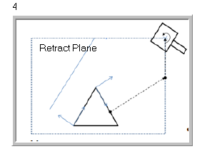
The following example outlines the basics of Automatic Safe Repositioning (ASR). This example is for an SR machine; the objective is to safely move the tool from one Transform Plane to another, both at different locations and orientations.
When rotary axes are repositioned during ASR on DCX machines, the control ensures the rotary axes are less than or equal to the length of the current tool away from the Y axis limit to prevent interference with the machine columns.
The following graphic shows the tool in the begin and target positions, as well as the retract plane and machine limits:
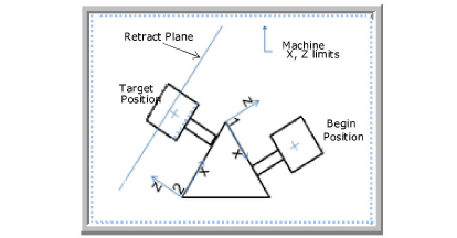
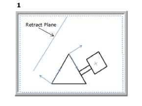
The tool starts in the begin position (1) and retracts along the tool vector (direction) to the machine limits, M140 (2):
|
|
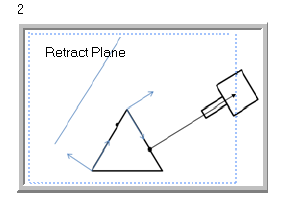
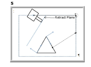
The tool retracts to the vertical (Z) machine limit (3) and then re-orients to the target position orientation (4):
|
|
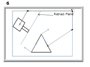
The tool tip moves to the retract plane (5) and then moves to a point above the plunge position in XY of the retract plane (6):
|
|
|
|
If the tool tip is not at or above the retract plane, program execution is stopped and an error message is generated. |

|
|
For DCX machines, refer to the X/Y Reorient Safety Type parameters in Machine Parameters – General 2 to understand how to safely reorient the axes to avoid collision. |

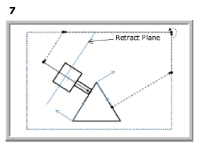
The tool plunges to the target position along the plunge direction (7):
Automatic Safe Repositioning Command Buffer Off (G08.2)
The G08.2 code turns off ASR Command Buffering. When the G08.2 command is called, the buffer state is turned off and the control outputs any buffered up machine commands (for example, preparatory functions, tool change, and so on).
|
|
The control will not output redundant commands after the ASR Command Buffer state is turned off. For example, if a rotary clamp was on before G08.1 and the clamp was toggled off and on several times, then finally set to off, G08.2 will only output one unclamp command. |

|
|
G31 Skip Function is not compatible with ASR Command Buffering. |

|
|
M00 (Program Stop) and M01 (Planned Stop) codes are skipped in ASR buffering mode. Codes are re-posted when buffering is no longer active, except in a Recovery/Restart. |

|
|
Restricting full ASR retracts requires understanding the machine motion illustrated in images 2 and 3 in Machine Movement. When the tool vector is aligned with the machine’s Z direction, the two movements are in the same direction, but both still execute in sequence. To restrict how far in Z the retract moves, specify both R and H parameters. The final Z position is the parameter that moved farthest from the part. |

|
|
When intelligent ASR is enabled in a program, G08.2 is not needed except to override intelligent ASR for particular data blocks. When G08.2 is used, intelligent ASR is effectively disabled, so active G08.2 parameters must be specified. |

There are two versions of ASR available. Option 1 is a simple retract, reorient and reposition to the specified location and orientation. Option 2 adds buffering of commands from a start block to an end block.
Format
The command format is as follows:
Option 1—Direct Reposition
G08.2 X_Y_Z_[I_J_K_ or A_B_C_][L_][D_][H_][P_][R_]
where
X_Y_Z_ are the target positions to move to.
I_J_K_ are the target tool vectors to reorient to. Cannot be used with A_B_C_.
A_B_C are the target rotary axes positions. Cannot be used with I_J_K_.
L_ is the incremental safety clearance distance along the tool vector to the target position. An error will be reported and the program will stop if the tool tip cannot clear this distance from the target position at the start of the final approach move.
D_ is the linearization override parameter that specifies how the control will reorient to the new tool vector or rotary angles. D0 forces linearization off; D1 forces linearization on. This parameter is optional; when not present the control uses the current linearization interpolation mode G43.4.
H_ is the Z axis limit this axis will travel during a full ASR move. Value is in machine coordinates and acts as a new Z axis limit the machine must reach before reorienting any rotary axes. This can be used to limit machine Z direction motion when ASR is changing tool vectors.
P_ is the W axis limit this axis will travel during a full ASR move. Value is in machine coordinates and acts as a new W axis limit the machine must reach before reorienting any rotary axes. This can be used to limit machine W direction motion when ASR is changing tool vectors. Note this only applies to machines that have a W axis present.
R_ is the tool vector retract distance traveled during a full ASR move. Value is an incremental distance from the start point along the tool vector when the tool is moving away from the part. This can be used to limit tool vector retract motion when ASR is changing tool vectors.
Option 2—Buffer Command Direct Reposition
G08.1 (ASR Command Buffering start; control begins buffering commands.
No physical motion until G08.2 is called.)
…
G0X_Y_Z_I_J_K_
G08.2 [L_][D_][H_][P_][R_] (ASR Command buffering end; control moves to the position and orientation prior to this block)
where
L_ is the incremental safety clearance distance along the tool vector to the target position. An error will be reported and the program will stop if the tool tip cannot clear this distance from the target position at the start of the final approach move.
D_ is the linearization override parameter that specifies how the control will reorient to the new tool vector or rotary angles. D0 forces linearization off; D1 forces linearization on. This parameter is optional; when not present the control uses the current linearization interpolation mode G43.4.
H_ is the Z axis limit this axis will travel during a full ASR move. Value is in machine coordinates and acts as a new Z axis limit the machine must reach before reorienting any rotary axes. This can be used to limit machine Z direction motion when ASR is changing tool vectors.
P_ is the W axis limit this axis will travel during a full ASR move. Value is in machine coordinates and acts as a new W axis limit the machine must reach before reorienting any rotary axes. This can be used to limit machine W direction motion when ASR is changing tool vectors. Note this only applies to machines that have a W axis present.
R_ is the tool vector retract distance traveled during a full ASR move. Value is an absolute distance from the start point along the tool vector when the tool is moving away form the part. This can be used to limit tool vector retract motion when ASR is changing tool vectors.
Tool Vector Canned Cycles with G08.2
NC canned cycles can be modified to execute along the current tool vector at a 3D point without having to define a full Transform Plane (G68.2). The G08.2 ASR Command can be used to re-orient the tool to a new tool vector after which the canned cycle can be commanded to execute along the new tool vector:
G08.2 X_Y_Z_I_J_K [H_][P_][R_](ASR move to start point and tool vector orientation)
G81 X_Y_Z_I_R_[P_Q_L_K_F_S_](e.g. Drill along current tool vector)
where
X_Y_Z_ are the target positions to move to.
I_J_K_ are the target tool vectors to reorient to. Cannot be used with A_B_C_.
A_B_C are the target rotary axes positions. Cannot be used with I_J_K_.
L_ is the incremental safety clearance distance along the tool vector to the target position. An error will be reported and the program will stop if the tool tip cannot clear this distance from the target position at the start of the final approach move.
D_ is the linearization override parameter that specifies how the control will reorient to the new tool vector or rotary angles. D0 forces linearization off; D1 forces linearization on. This parameter is optional; when not present the control uses the current linearization interpolation mode G43.4.
H_ is the Z axis limit this axis will travel during a full ASR move. Value is in machine coordinates and acts as a new Z axis limit the machine must reach before reorienting any rotary axes. This can be used to limit machine Z direction motion when ASR is changing tool vectors.
P_ is the W axis limit this axis will travel during a full ASR move. Value is in machine coordinates and acts as a new W axis limit the machine must reach before reorienting any rotary axes. This can be used to limit machine W direction motion when ASR is changing tool vectors. Note this only applies to machines that have a W axis present.
R_ is the tool vector retract distance traveled during a full ASR move. Value is an absolute distance from the start point along the tool vector when the tool is moving away form the part. This can be used to limit tool vector retract motion when ASR is changing tool vectors.
Exact Stop (G09)
G09 applies an exact stop to the specific move on the same line. Since G09 is non-modal, it must be programmed in every block that requires the tool to come to a complete stop.
Modal - No
|
|
G09 is used in conjunction with G00 - Rapid Traverse (default), G01 - Linear Interpolation or G02/G03 - Clockwise/Counterclockwise Arc commands. |

Format
G09 X____ Y____ Z____ (machine decelerates to stop at specified point)
Disable Auto Rotary Clamp (G216.2)
Disable Auto Rotary Clamp (G216.1) prevents the rotary clamp from automatically turning on when an axis is unclamped with the M code for the specific axis (Unclamp C-axis M13, Unclamp B-axis M35, Unclamp A-axis M33).
|
|
G216.2 only disables the auto rotary clamp if the axis is already unclamped using the correct M code. |
Enable Auto Rotary Clamp (G216.1)
Enable Auto Rotary Clamp (G216.1) cancels Disable Auto Rotary Clamp (G216.2).