Lead In/Out Moves
With posted NC programs, use Lead In and Lead Out moves to control the tool path before the tool moves into position to cut the part.
A positive Lead Angle starts the tool path away from the programmed path when performing a Lead In move and ends away from the programmed path when performing a Lead Out move. A negative Lead Angle has the opposite effect.
Toolpath Graphics will not draw the Lead Angle or Lead Length motion.
|
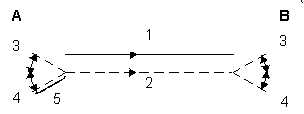
A |
Lead In move |
|
B |
Lead Out move |
|
1 |
Programmed paths |
|
2 |
Offset tool path |
|
3 |
(-) Lead Angle |
|
4 |
(+) Lead Angle |
|
5 |
Lead Length |
When you select Milling Type Left, Right, Inside, or Outside, and enable the Display APT fields in Editor field on the Utilities—Post Processor screen, Lead Angle and Lead Length fields appear on the Milling data block.
Lead In/Out moves are determined by the lead angle and lead length values. With the exception of open contours, perform a 90º arc Lead In and Lead Out move.
These NC Programming fields operate similarly to Conversational Blend In/Blend Out moves (Blend Offset and Blend Overlap values).
Lead Angle
Lead Angle is used with Lead Length to define Lead In and Lead Out moves. Lead Angle is an angle relative to the direction of the cut, measured 180º from the end of the first segment.
If starting a contour in the middle of a line or arc, set the Lead Angle at 45º or 90º to prevent gouging the contour.
Use caution with Lead Angle, because the tool could gouge the part if left at the default of 0.
Lead Length
Lead Length is used with Lead Angle to define Lead In and Lead Out moves. Lead Length is the length of the Lead In move.
The Lead Length must be larger than the tool's radius. For example, using a 1" diameter End Mill, the Lead Length would be 0.505".