Helical Plunge (Ramp)
To use Helical Plunge, the Helical Ramp software option must be installed.
The Helical Plunge programming option provides helical plunging as an alternative machining strategy. Helical plunge and straight plunges can be used separately for roughing and finishing phases, or they can be used together for the same operation. For example, you can rough with a helical plunge and finish with a straight plunge.
With Helical Plunging, the tool rotates around the cut and moves down the Z-axis. The cutting tool is continuously cutting deeper and enters and exists the machined part only once.
The Helical Plunge fields are located on the Milling 2 tab on the Program Parameters screen. Set Mill Plunge Type and/or Finish Plunge Type to Helix. Specify the ramp slope and radius percentage.
|
|
|
Helical Plunge Milling Parameter Fields
Helical Plunge (Inside/Outside) for Mill Frames, Mill Circles and Ellipses
Helical Plunge with UltiPockets
Helical Plunge with Operator Specified Location
Helical Plunge in the Center of a Pocket
Helical Plunge with Outward Pocketing
Helical Plunge of Mill Frame Inside with No Pecking and Blend Offset
Helical Plunging of Mill Frame Inside with Pecking and Straight Plunge Finish Pass and Blend Offset
Helical Plunge with Lines and Arcs
Helical Plunge with 3-D Part Programming Option
Helical Plunge Milling Parameter Fields
On the Program Parameters screen, Milling 2 tab, select Helix in the Mill Plunge Type field.
The Field Name Glossary contains definitions of all WinMax fields. The fields listed below appear on the Milling 2 (Helical Plunge) screen. Fields displayed on screen may vary according to machine type, configuration, parameter settings, and/or settings in other fields.
|
|
Helical Plunge (Inside/Outside) for Mill Frames, Mill Circles and Ellipses
Helical Plunge is similar for milling the inside or outside of mill frames, circles, and ellipses (with or without blend-in moves). The center location of the helical plunge is the same as a straight plunge. The direction of the helical plunge (clockwise, CW, or counter clockwise, CCW) will be determined by the tool spin direction (CW or CCW) and the milling direction (climb or conventional). If Blend Offset is used, the helical plunge will be centered about the plunge point of the Blend Offset.
The helical plunge direction that provides a smooth transition to the tool path will be chosen. Helical plunge is not allowed when Milling Type On is selected.
Helical Plunge with UltiPockets
The Helical Plunge option is used with the UltiPocket option to define the plunging location when inward pocketing. The operator can specify the pocket plunge location using the Operator Specify Pocket Start function, or start the pocket plunge near the center by using the Inward Pocket Plunge Near Center function. See Helical Plunge with UltiPockets in Conversational Programming.
When both the Operator Specify Pocket Start and the Inward Pocket Plunge Near Center are set to No, the plunge locations are used that would have been used without the Helical Plunge option.
|
|
An error message appears if the plunge point specified would violate the programmed part surface. |
Helical Plunge with Operator Specified Location
When the operator specifies the plunge point, all of the helix plunge moves will occur at that location, even for the pocket boundary.
Helical Plunge in the Center of a Pocket
When the Inward Pocket Plunge Near Center field value is Yes (Operator Specify Pocket Start value must be No), a plunge point near the center of the pocket will be chosen. Islands near the center will impact upon the plunge point’s location.
|
|
When machining a part with a lot of webbing (many small pockets separated by walls), it may be desirable to disable helical plunging. |
Helical Plunge with Outward Pocketing
Helical plunging occurs near the center of the pocket when used with Outward Pocketing, and only one plunge location is needed. The Operator Specify Pocket Start and the Inward Pocket Plunge Near Center fields have no effect on Helical Plunge with Outward Pocketing.
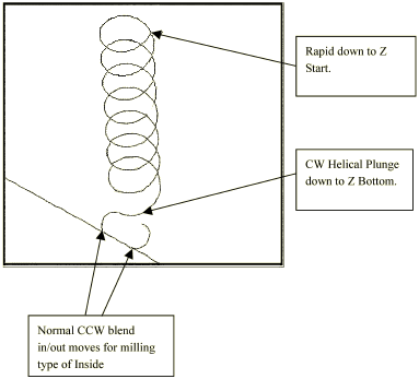
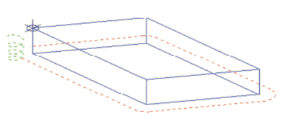
Helical Plunge of Mill Frame Inside with No Pecking and Blend Offset
The tool will helical plunge to the Z Bottom level and then perform the normal blend-in move. The direction of the helical plunge arc will smoothly transition to the blend-in arc. For instance, if the blend-in arc is CCW, the direction of the helical plunge will be CW. The following isometric views are created by setting the Draw Plunge Moves graphics parameter field to Yes.
|
|
This graphical representation is only for informational purposes and cannot be viewed with WinMax. |
The graphics show the finish pass only if a finish tool is specified in the frame block, and do not show individual peck levels.
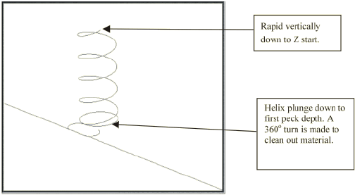
Helical Plunging of Mill Frame Inside with Pecking and Straight Plunge Finish Pass and Blend Offset
The following example is a Mill Frame Block Type with Inside Milling Type. The finish tool specified and the peck depth is set to 0.6 inches.
First Peck - The tool helical plunges down to the -first peck depth, then mills another full circle to ensure that all material down to the first peck is removed. After the full circle is completed, a 180° blend in arc is performed. The direction of the helical plunge will always be in the opposite direction of the blend-in arc.
|
|
These graphical representations are only for informational purposes and cannot be viewed with WinMax. |
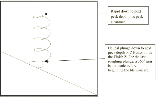
Second Peck and All Pecks to Finish Peck Depth - The tool will rapid down to the previous peck depth plus the peck clearance plane. The tool then helical plunges down to the next peck depth or the Z Bottom plus the Finish Z. If the tool is at a peck depth, a 360o arc will be machined. The 360o arc will not be machined if it is the last peck depth. Instead, a blend-in arc will be machined. The blend-in arc for the last peck depth will be similar to the one machined for the first peck.
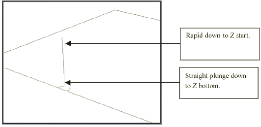
Finish Pass - The tool will rapid down to the Z Start and plunge feed down to the Z Bottom. A blend-in move is performed before milling the frame contour.
|
|
When helical plunge is used for roughing passes, a large amount of material is removed around the point of entry. Therefore, using helical plunging for the finish passes is probably not necessary. |
|
|
If the finish tool is larger than the roughing tool, helical plunges should also be performed for the finish pass. If a post was created by the roughing tool (the Helix plunge radius was greater than 50 percent) the finish tool may be cutting into the post. |
Helical Plunge with Lines and Arcs
Helical plunge with lines and arcs occurs at the start of the contour.
The following example shows helical plunging with right cutter compensation of a contour.
|
|
An error message will be displayed if the helical plunge would cut into a part surface. If this error message appears, move the starting location of the contour to an area that will not cause interference. |
Helical Plunge with 3-D Part Programming Option
Helical plunging is supported in the 3-D Part Programming option. A helical plunge can be performed when the Mill Plunge Type field is set to Helix.
Only one helical plunge occurs when using a bi-directional tool path. When performing helical plunge using unidirectional tool path, a helical plunge occurs for each cutter pass.
|
|
When programming complex 3-D parts, the operator should review helical plunge placements in graphical form before milling to ensure helical plunges from one block do not interfere with neighboring blocks. If Mill Plunge Type field is set to Helix, but the helical plunge does not appear on the graphics screen, check the Z Start field on the Mill 3-D block screen. The plunges may not appear if Z Start value is too low. |