Tool and Radius Offsets (G40–G49)
Tool and Radius Offsets include the Tool Length Offsets and Tool Radius Offsets. Cutter Compensation G codes G40–G42 are used to control tool movement. Access the Tool Offsets from the Tool Setup screen. Select the Tool Offsets (F4) softkey. From the Tool Setup - NC Tool Offsets screen, select either Tool Length Offsets (F4) or Tool Radius Offsets (F4). The softkey toggles between these selections.
-
The Length Offset Table contains the tool length offset (G43, G44).
-
The Radius Offset Table holds signed values for cutter compensation (G40–G42) and Tool Radius Offset Increase/Decrease (G45–G48).
The measurement units for the offsets in the Tool Offset Table depend on the programmed units. If -9.5 is entered for tool offset 15, that tool offset is -9.5 inches (or -9.5 mm, depending on the unit of measurement).
The Toggle Units softkey on the NC Tool Offsets screen changes the units of measurement between inch and metric.
Use either the Page Up and Page Down softkeys, the PAGE UP and PAGE DOWN keys, or the scroll bar to scroll through all of the Tool Offset fields. The keyboard up and down arrows move through the fields displayed on the screen.

|
Tool changes may be made from the offsets table screen. Place the cursor in the offset field of the tool you wish to change to, and press the console Auto Tool Change button. |
Tool Length Offset (G43, G44, G49)
Cutter Compensation (G40–G42)
Cutter compensation may be used for two purposes. First, it may be used when the dimensions in the program and the part surface are the same. The system calculates the proper tool path by using the part surface and the tool diameter information.
Second, cutter compensation corrects the difference between the diameters of the tool specified and the tool actually used to cut the part. This situation often occurs when the program originates from an off-line device. Note that the coordinates of those programs are usually tool center line data.
|
|
If the first segment in a contour is an arc with a radius smaller than the radius of the tool, the control will generate an error message indicating that you need to use a tool with a smaller radius or program a larger radius. |
Cutter compensation is based on the direction of travel of the tool. To determine which type of cutter compensation to use, look at the part as if you are moving around the part always keeping the tool ahead of you. Then it becomes obvious whether the tool needs to be on the right or the left of the programmed line or the boundary of the part as shown in the illustration below.
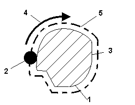
|
1 |
Part |
|
2 |
Cutter |
|
3 |
Programmed Part Outline |
|
4 |
Direction of Cutter Travel |
|
5 |
Compensated Cutter Path |
Cutter Compensation – ISNC and Basic NC
You may program cutter compensation using ISNC or Basic NC.
Tool Radius Offset
ISNC
There are two options to program cutter compensation using ISNC:
-
Use Diameter and Diameter Wear values from Tool Setup. To use this method, the Diameter Compensation Using Tool Setup parameter in NC Settings must be set to Yes. The control will use the values from Tool Setup to calculate the offset.
-
Use a D code (Tool Radius offset). The D code specifies an index into the Tool Offset Table or an actual offset value. For example, in the command G41 D5, the index value is an actual offset value of 5.
|
|
If a D code is present, it always takes priority over the Diameter and Diameter Wear method, even if the Diameter Compensation Using Tool Setup parameter is Yes. |
|
|
An error will be generated if there is a decimal point. Access the Tool Radius Offset Table using the Tool Offset softkey on the Tool Setup screen. The Tool Radius Offset page contains 200 registers for storing radius offsets. |
Basic NC
To program cutter compensation using Basic NC, you may choose whether or not to use a D code:
-
Use Diameter and Diameter Wear fields from the Tool Setup screen. If a D code is not present the control will always use Diameter and Diameter Wear.
-
Use a D code. Basic NC interprets the D code value based on whether you are calling out a tool change or commanding a G41 or G42:
-
If you use a D code when calling out a tool change, enter the actual tool diameter. Basic NC divides this value by two to calculate the tool diameter offset.
-
If you are programming a G41 or G42 code, Basic NC interprets the D code based on whether the D code value contains a decimal point:
-
Contains a decimal point – Basic NC interprets the D value as the tool diameter offset.
-
Does not contain a decimal point – Basic reads the D value as an index value for the Tool Offset table.
-
-
Tool Length Offset
You may use a G43 code to program tool length offsets. This is true for ISNC and Basic NC. Use an H code to specify an index into the Tool Offset Table. For example, in the command G43 H01, the index value is “01”.
The value in the Tool Offset Table is a negative value that represents the distance from the Z home position to the top of the part with the tool tip touching the top of the part.
|
|
Another way to program a tool length offset would be to use the Zero Calibration field in the Tool Setup screen, and not use the G43 H code. This is recommended, especially if you are using the Tool Probing software. |
Cutter Compensation Off (G40)
The Cutter Compensation Off code (G40) is the default. It cancels cutter compensation by erasing all the data in the system’s cutter compensation look-ahead buffers and moving to the current uncompensated endpoint at the programmed feedrate.
G00 or G01 must be selected in order for this command to cancel the offset compensation. Each axis moves straight (G01) or at rapid traverse (G00) from the point of the old vector at the start point toward the end point. The machine should be in G40 mode before the end of a program. Otherwise, when the program ends in the offset mode, positioning cannot be made to the terminal point of the program, and the tool position will be separated from the terminal position by the vector value.
Format
The command format for Cutter Compensation Off is as follows:
G40 X____ Y____
where
If the parameters are omitted, the tool moves the old vector amount in the opposite direction which effectively cancels the offset.
|
|
It is possible to switch from left to right cutter compensation (and vice versa) without first canceling cutter compensation. |
Cutter Compensation Left (G41)
The Cutter Compensation Left code (G41) switches on cutter compensation. It establishes a new tool path left and parallel to the programmed path. The distance between the new tool path and the programmed path is equal to the cutter compensation value for the programmed tool.
G41 is canceled by G40.
The offset executes only in the G17 offset plane. In simultaneous three-axis control, the tool path projected on the offset plane is compensated.
G00, G01, G02, or G03 must be specified.
Format
The command format for cutter compensation left is as follows:
G41 X _____ Y_____ D_____
where
If the offset number for cutter compensation is D00, the system will not go into G41 mode.
|
|
G41 cannot be used when G42 or G41.2 are active. |
|
|
Tool Vector orientation cannot be changed when G41 is active. |
3D Tool Geometry Compensation (G41.2)
3D Tool Geometry Compensation (G41.2) allows the specification of the Surface Contact Point, Surface Normal Vector, and Tool Vector for ball nose, flat end, and bull nose endmills. See 3D Tool Geometry Compensation (G41.2) discussion in Tool Centerpoint Management (M128) for more information.
|
|
G41.2 cannot be used when G41 or G42 are active. |
Cutter Compensation Right (G42)
The Cutter Compensation Right code (G42) switches on cutter compensation and establishes a new tool path right of and parallel to the programmed path. The distance between the new tool path and the programmed path is equal to the cutter compensation value for the programmed tool.
G42 is canceled by G40.
This command is an offset method similar to G41 except that the offset is to the right of the programmed path looking in the direction in which the tool is advancing. The offset is performed only in the G17 offset plane. Only the coordinate values of an axis in the offset plane are affected by the offset. In simultaneous three-axis control, the tool path projected on the offset plane is compensated.
G00, G01, G02, or G03 must be specified.
Format
The command format for cutter compensation right is as follows:
G42 X _____ Y_____ D_____
where
If the offset number is D00, the system will not go into G42 mode.
|
|
G42 cannot be used when G41.2 is active. |
|
|
Tool Vector orientation cannot be changed when G42 is active. |
Cutter Compensation Programming
Follow these steps to use cutter compensation:
-
Enter the part surface description according to the final dimensions of the part.
-
Enter the full cutter diameter as a positive number in the Diameter Compensation field in Tool Setup, or supply a D word when changing tools (Basic NC only).
-
Activate cutter compensation in the desired direction (left or right of part surface with respect to tool path direction).
-
Supply an entry move from somewhere outside the part to the start point of the part surface, i.e., somewhere outside of the compensated path. The part surface appears as a blue line on the graphics display.
-
Following all of the blocks to be compensated, provide an exit move to somewhere outside the compensated path and turn off cutter compensation (G40). When a G40 is programmed, cutter compensation extracts any remaining information from its look-ahead buffer and moves to the last programmed end point. The tool moves from the compensated end point of the previous move to the end point of the exit move.
-
Be certain that the exit move is outside the compensated path. Otherwise, turning off cutter compensation may cut into the part surface. To check the exit move, use graphics to verify the tool path movements.
The tool moves from the start point of the entry move and ends at the compensated start point for the part surface as shown in the graph below:
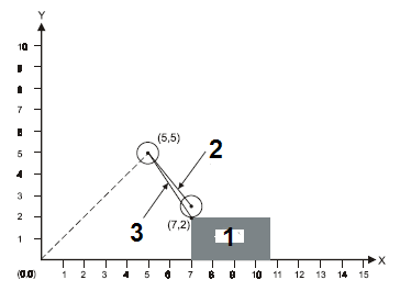
|
1 |
Part |
|
2 |
Actual Tool Path |
|
3 |
Programmed Move |
In the previous illustration, the value in the Diameter Compensation field is 1.00, and these codes were used to control tool movement:
-
G00 G40 X5. Y5.
-
G41 X7. Y2.
|
|
Z movements may be used for the entry and exit moves. For example, turn on cutter compensation when moving to a Z Start plane before plunging. Turn off cutter compensation after retracting the tool from the part. |
|
|
Turn off cutter compensation using a G40 code before ending a program or all programmed blocks may not be cut. |
|
|
Refer to NC Parameters for information about the DEFAULT CUTTER COMP LOOK AHEAD field in the NC Parameters screen. |
Tool Length Offset (G43, G44, G49)
Tool offsets, G43 and G44 tool length compensation codes, are used to compensate tool length without altering the NC program. G43 is for positive tool length compensation. G44 is for negative tool length compensation. Either the G49 command, or an H00 command, immediately cancels the offset.
The tool offset specified by a G43 or G44 overrides the tool length offset from the Zero Calibration field on the Tool Setup screen. The Zero Calibration field on the Tool Setup screen is always treated as a negative Z offset. For example, if a value of 3.0 is put in the Zero Calibration field, a Z offset value of -3.0 is stored. If the command G43 H1 is then used where the value -2.2 is stored in the H1 offset register, WinMax uses a tool offset of –2.2. The table below illustrates tool offsets:
|
Tool Setup Screen Zero Calibration |
Tool Length Offset Mode |
H1 |
Total |
|---|---|---|---|
|
3.0 |
G43 |
-2.2 |
-2.2 |
|
3.0 |
G44 |
-2.2 |
+2.2 |
|
3.0 |
G49 |
-2.2 |
-3.0 |
|
3.0 |
G49 |
+2.2 |
-3.0 |
|
3.0 |
G43 |
+2.2 |
+2.2 |
|
3.0 |
G44 |
+2.2 |
-2.2 |
Tool Offsets
|
|
The values in the Tool Setup screens always remain in the units selected when going into the NC Editor. |
For Basic NC (BNC)
An H address may specify an index into the tool length offset table without specifying a G43 or G44. In such a case, the value in the tool length offset table is used as the tool offset. This is equivalent to the Zero Calibration field on the Tool Setup screen.
For BNC and ISNC, if the system is in the G43 and G44 mode already, an H code can be used by itself to replace the existing tool length already in effect.
|
|
If no G43 or G44 is programmed and an H offset is not specified, tool lengths are taken from the Tool Setup screen. An offset in the X axis can be specified with the G19. An offset in the Y axis can be specified with the G18. If a G17 is provided, or none of the plane selection commands (G17, G18, and G19) is present, specify an offset in the Z axis. The G17, G18, and G19 used in this block are only used to specify the axis of the tool offset and will not affect the specified plane. An offset in the X or Y axis cannot be specified when cutter compensation is active or commands G45–G48 are being used. Commands G45–48 support existing X or Y axis tool offset programs; however, to save time, automatic Cutter Compensation (G40–G42) should be used instead. Commanding an H00 cancels an offset. Either G43 or G44 is in effect until a G49 or H00 is used. |
Format
The H is the Offset Code with a range of H00 to H200. G17 is optional when a Z axis offset is desired.
The following four examples illustrate tool length offset H codes with the G43 and G44 codes. Tool 1 had a value of 5.0 for the Zero Calibration field on the Tool Setup screen. The Tool Length Offset 1 value is –6.0 and the Tool Length Offset 2 value is –7.5.
Example 1
Example 2
Example 3
Example 4
T01 M06 - sets the tool length to be 5.0
H02 - tool length remains 5.0
G43 - tool length remains 5.0
H02 - sets the tool length to be 7.5
5-Axis Linear Interpolation (G43.4)
The CNC offers two rotary interpolation modes of the tool relative to the Workpiece Coordinate System. Refer to Getting Started with WinMax Mill.
-
Linearly interpolate the Tool Vector with respect to the Workpiece Coordinate System between tool positions. Refer to Getting Started with WinMax Mill.
|
|
Ensure the tool start point is relatively close to the C-axis centerline location immediately before activating the G43.4 command. When executing a Tilt Axis Preference command, the machine may need to rotate the part up to 180° around the machine singularity point when moving to the contouring start point and tool orientation. Refer to Tilt Axis Preference (M200). If the tool start point is too far away from the C-axis centerline, an “Axis out of limits” error will occur. |
-
Linearly interpolate the programmed rotary angle between tool positions.
Format
|
|
The 0 and 1 parameters for G43.4 are optional. If you do not choose a parameter, the control will automatically choose:
|
G43.4 Q{0, 1} will turn on the 5-axis workpiece-relative linear interpolation.
G43.4 Q0 linearly interpolates the Tool Vector and Tool Tip between NC points with respect to the Workpiece Coordinate System. Refer to Getting Started with WinMax Mill.
|
|
Although G43.4 Q0 will interpolate the Tool Tip and Tool Vector relative to the Workpiece Coordinate System, the CAM software must generate properly toleranced tool paths to machine smooth surfaces. |
G43.4 Q1 linearly interpolates the Tool Tip between tool positions with respect to the Workpiece Coordinate System and the rotary angles in the Machine Coordinate System. Refer to Getting Started with WinMax Mill.
|
|
Even with G43.4, the surface finish is still highly dependent on the CAM software to generate enough tool positions to properly break up rotary transitions (i.e., Tool Vector transitions) and tolerance the Tool Tip linearization of the surfaces being cut. This concept is similar to using G01 moves to cut 3D surfaces in 3-axis machining, but even more critical since the Tool Vector orientation may change. |
Tool Radius Offset (G45–G49)
|
|
ISNC and Basic NC – the tool used for cutter compensation must be smaller than or equal to the arc that you have programmed. If the tool radius is greater than or equal to the arc radius, the compensated tool path will sweep in the opposite direction of the programmed arc. |
Tool position offset commands increase or decrease the amount of axis movement. Offset values within the following ranges can be selected for the tool radius offset commands:
|
|
mm input |
inch input |
|
Offset Value |
0~±999.999 mm |
0~±99.999 in. |
|
|
0~± 999.999° |
0~±999.999° |
|
|
G45–48 support existing X or Y axis tool offset programs. However, to save time, use the automatic Cutter Compensation (G40-G42) instead. |
Tool Radius Offset Increase (G45)
This command increases the specified block’s tool radius offset amount by the value stored in the offset value memory.
Tool Radius Offset Decrease (G46)
This command decreases the specified block’s movement amount by the value stored in the offset value memory.
Tool Radius Offset Double Increase (G47)
This command increases the specified block’s movement amount by twice the value stored in the offset value memory.
Tool Radius Offset Double Decrease (G48)
This command decreases the specified block’s movement amount by twice the value stored in the offset value memory.
Tool Offset Cancel (G49)
This command cancels the offset.
Format
The command format for the tool position offsets is as follows:
GXX X_____Y_____Z_____A_____B____C____ D____
where
GXX is an optional Interpolation (Group 1) move command, and D is the offset command. The number which follows D is an index into the tool offsets table. The offset value is modal and needs to be specified only once. The offset is applied to all axes specified in the parameters.
Example
Set tool offset 1 to the desired offset before running the following program using the Tool Radius Offset commands (G45 through G48):
Industry-Standard NC Part Program 1 Inch
G45_G48.FNC
%
N10 G10 P1 R0.5
N20 G00
N30 G90
N40 M25
N50 T1 M06
N60 Z5.0 X0. Y0.
N70 S2000 M03
N80 Z0.05
N90 G00 Z-0.5 F10.
N200(INNER OUTLINE WITHOUT USING OFFSETS)
N210 G91 X4 Y4
N220 G01 X3
N230 Y1.5
N240 X4
N250 G45 Y-1.5
N260 X3
N130 G03 X1 Y1 I0. J1
N140 G01 Y4
N150 X0
N160 G02 X-2 Y2 I0. J2
N170 G01 Y0
N180 X-3
N190 Y-2.5
N200 X-3
N210 Y2.5
N220 X-3
N230 G03 X-1 Y-1 I0. J-1
N240 G01 Y-2
N250 X1
N260 Y-4
N265 Z5.05
N270 G00 X-4 Y-4
N275 G90 X0 Y0
N280(OUTER OUTLINE USING G45, G46, G47, AND G48)
NC Part Program 2 Inch
G45_G48.FNC
N290 G91 G46 X4 Y4 D1
N300 G47 G01 X3 F20.
N305 Y1.5
N307 G48 X4
N308 Y-1.5
N309 G45 X3
N310 G45 G03 X1 Y1 I0. J1
N320 G45 G01 Y4
N330 G46 X0
N340 G46 G02 X-2 Y2 I0. J2
N350 G45 G01 Y0.
N360 G47 X-3
N370 Y-2.5
N380 G48 X-3
N390 Y2.5
N400 G45 X-3
N410 G45 G03 X-1 Y-1 I0. J-1
N420 G45 G01 Y-2
N430 X1
N440 Y-4
N450 G00 G46 X-4 Y-4
N460 G00 Z5.05
N470 M25
N480 M05
N490 M02
Scaling (G50 and G51)
The G51 code is used to scale subsequent move commands by a programmable scale factor and must be in an independent block.
Scaling is not applicable to the following movement in case of canned Z axis movements. If scaling results are rounded and units less than 5 are ignored, the move amount may become zero and may affect cutter movement. Whether the scaling function is effective or not, it can be set by a parameter for each axis. The scaling function always becomes effective for the circular radius command R in the G51 mode, regardless of these parameters.
One or more axes’ scaling can be disabled on the NC Parameters screen. The methods for specifying the scaling center point and the scaling factor are different with BNC and ISNC.
For BNC, X, Y, and Z are the scaling center points in absolute coordinates. The I, J, and K codes specify the scale factor for the X, Y, and Z axes. If only I is specified, all axes will be scaled by that factor. Scaling G51 codes may not be nested.
For ISNC, these two methods can be used to specify scaling parameters:
Method 1: X, Y, or Z present. X, Y, Z define the scaling center point. If I, J, or K are present, they define the scaling factors. If they are absent and P is present, the P value defines the scaling factor for all three axes. If P is an integer (no decimal point) the value is multiplied by the least scaling factor parameter on the NC Parameters screen; otherwise, the exact P value is used.
Method 2: X, Y, or Z absent. I, J, K define the scaling center point. P provides the scaling factor if provided for all three axes. If P is an integer (no decimal point) the value is multiplied by the least scaling factor parameter on the NC Parameters screen; otherwise, the exact P value is used.
Format
The format of the BNC scaling code is as follows:
G51 X___ Y___ Z___ I___ J___ K___
where
The format of the ISNC scaling code is as follows:
|
|
The smallest unit of scaling is either 0.001 or 0.00001 when an integer P value is provided. The Least Scaling Factor field on the Configuration Setup screen is used for setting the smallest unit of scaling. |
Example
Here is a BNC sample using the scaling codes:
Using G91 — G00 X20. Y20.
G51 X40. Y40. I.5
G01 X40.
Y40.
X-40.
Y-40.
G50
The following diagram illustrates the previous code sample:
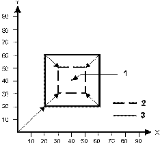
|
1 |
Centerpoint |
|
2 |
Scaled |
|
3 |
Original |
|
|
The Scaling (G51) command must always be canceled with a Cancel Scaling (G50) command. |
Mirror Image (G50.1 and G51.1)
Mirroring (G51.1) and Mirroring Cancel (G50.1) commands are used when the shape of the workpiece is symmetric to an axis. The whole part can be prepared by programming a subprogram and using programmable mirror imaging. Ordinary mirror image comes after the programmed mirror image. The first movement command must be absolute when in this mode. The following actions occur when the mirror image is applied to only one axis composing a plane:
-
Circular Command: CW and CCW are reversed.
-
Cutter Compensation: Right and Left Offset are reversed.
-
Coordinate Rotation: Rotation angle becomes reversed.
Format
The formats of the mirroring codes are as follows:
G51.1 X___ or Y___ or Z___
G50.1 [X0] or [Y0] or [Z0]
where
X is the X-axis Dimension
Y is the Y-axis Dimension
Z is the Z-axis Dimension
Specifying a G50.1 with no X, Y, or Z parameter cancels the mirroring code in the X, Y, and Z axes. The coordinates about which the tool path will be mirrored are in absolute values. The mirroring codes create the following special conditions:
•For circular commands CW and CCW are reversed.
•Cutter compensation for Right and Left are reversed.
•Mirroring G51.1 codes may not be nested.
G51.1 is used to mirror a tool path about the X, Y, or Z axis while G50.1 is used to cancel mirroring for the X, Y, or Z axis.
|
|
This mode is canceled by G50.1. The first movement command after a G50.1 command must be an absolute command. This mode must not be specified in the G68 or G50 mode. |
Example
In the illustration below, part #1 (in the upper right corner) is mirrored three times into part #2, #3 and #4. Note that the direction of the tool path (shown as directional arrows numbered 1, 2, and 3) on each part changes with each mirroring operation:
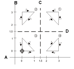
|
A |
X Axis |
|
B |
Y Axis |
|
C |
X Mirror Axis |
|
D |
Y Mirror Axis |
The following program example mirrors the part as shown in the example from the previous page:
NC Part Program 1 inch
MIRROR.FNC
%
N10 (FIG 7-94 MIRRORING EXAMPLE)
N42 ( )
N44( MAIN PROGRAM )
N46 ( )
N50 M98 P8888
N60 (2-PART#1 MIRRORING IN X)
N70 G51.1 X1.5
N80 M98 P8888
N90 (3-MIRRORING CONTINUED IN Y)
N100 G51.1 Y1.5
N110 M98 P8888
N120 (CANCEL INITIAL X & Y MIRROR)
N130 G50.1
N140 (4-PART#1 MIRRORED IN Y)
N150 G51.1 Y1.5
N160 M98 P8888
N170 M02
N172 (END OF MAIN PROGRAM)
N180 ( )
N190 (SUB-PROGRAM 8888)
N200 (1-PART#1 UPPER RIGHT)
N210 (TRIANGLE 3,2 3,3 2,3)
N215 ( )
O8888
N230 G00 G90 T01 M06
N240 X0 Y0 Z.05 M03 S800
N250 G00 X3 Y2 Z0
N260 G1 Y3 F50
N270 X2
N280 X3 Y2
N290 M99
E
Local Coordinate System Setting (G52)
While programming in a work coordinate system, it is sometimes more convenient to use a local coordinate system within the current work coordinate system. The zero point of each local coordinate system is equal to the X, Y, Z, position of the current work coordinate system. The local coordinates are relative to the workpiece coordinate system, including any skew that may be active at that time. A, B, C angles are not rotations with respect to the workpiece coordinate system, but are rotary axis positions that rotate the local coordinate system around each rotary axis centerline.
To cancel the local coordinate system, the zero point of the local coordinate system should be matched with the zero point of the work coordinate system by using the G52 X0 Y0 Z0 command. The local coordinate system can also be canceled by switching to another work coordinate system (including the current work coordinate system) or to the machine coordinate system (G53).
The G52 command is most useful in conjunction with subprogram commands. A subprogram could be used to cut a part and the local coordinate system can be shifted to cut a number of similar parts.
Format
The format of the local coordinate system command is as follows:
G52 X_____Y_____Z_____A____B____C____
where
Example
This illustration shows setting a local coordinate system using the G52 command:
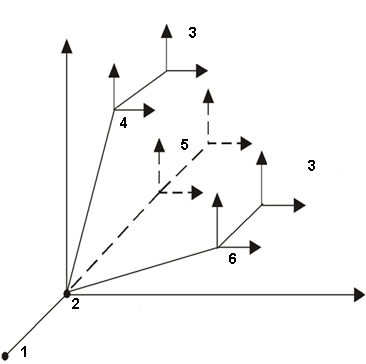
|
1 |
Machine Zero Point |
|
2 |
Shift Offsets |
|
3 |
Local Coordinate System |
|
4 |
G54 |
|
5 |
G55 through G58 |
|
6 |
G59 |
The following is a sample program, which uses G52 to set local coordinates:
NC Part Program 1 Inch
LOC_COOR.FNC
%
N10 G00 G90
N40 M25
N45 X0 Y0
N50 T1 M06
N60 Z5.
N90 S2000 M03
N100 Z0.05
N110 M98 P2121
(USE LOCAL COORD SYSTEM)
N240 G52 X-1.5 Y-1.5
N320 G65 P2121
N380 G52 X1.5 Y-1.5
N390 M98 P2121
N430 G52 X0 Y-3
N440 M98 P2121
N430 Z5.
N1170 M25
N1190 M05
N1200 M02
O2121
N500 X1
N510 Y1
N520 X0
N530 Y0
M99
Machine Coordinates (G53)
This Machine Coordinates (G53) command moves the tool to the X, Y, Z, A, B, C machine coordinate position at rapid traverse. This command is only effective in the block in which it is specified and in Absolute mode (G90). The system reverts to the last commanded work coordinate system.
If a local coordinate (G52) is used before a machine coordinate (G53) is commanded, the local coordinate is canceled when the system goes back to the last commanded coordinate system. Reinstate the local coordinate system with another G52.
Format
The format of the machine coordinates command is as follows:
G53 X____Y____Z____ A ____ B ____C____
where
Example
Before running this sample program, set the shift offsets to X0 Y0 Z0 and set part zero to X2.0 Y3.0 and Z1.0.
%
G00 G90
M25
X0 Y0
T1 M06
Z5.
S2000 M03
Z0.05
G01 X1 F30.
Y1
X0
Y0
(USE MACHINE COORD SYSTEM)
G01 G53 X0
G53 X1 F30.
G53 Y1
G53 X0
G53 Y0
G53 G00 Z5.
M25 M05
M02
E
|
|
When running a program on the control, do not use negative shift offsets with G28 or G53. An error message will occur since the negative machine positions cannot be implemented. |
Multiple Work Coordinate Systems (G54–G59)
These modal commands select the work coordinate systems 1–6. The work coordinate systems are affected by the work offsets, the shift offset, and the G92 (Set Part Zero) command. Coordinate system 1 is the same as the part setup and it is the default coordinate system. Coordinate systems 1–6 are established by manually entering work offset values for G55–G59 on the Work Offset screen or with the G10 command.
Use the G10 command to set tool offsets, enter tool wear data, and change work coordinate systems, and use the G92 command to set part zero. All six work coordinate systems can be moved an equal distance and direction by using the G92 command.
Format
The format of the multiple work coordinates command is as follows:
G54 (Select work coordinate system 1)
G55 (Select work coordinate system 2)
G56 (Select work coordinate system 3)
G57 (Select work coordinate system 4)
G58 (Select work coordinate system 5)
G59 (Select work coordinate system 6)
Example
When in the NC mode, the Part Setup screen has the Work Offsets (F1) softkey to display up to six work coordinates (G54–G59) and a set of shift offset values. As shown below, these codes are used to set multiple part zeroes for multiple parts fixtured to the table and milled consecutively using the same part program.
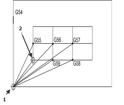
|
1 |
Machine Zero |
|
2 |
Part Zero |
The coordinates defining G54 are the part zero coordinates for the original part defined on the Part Setup screen. Set the X, Y, and Z values for the G54 to G59 codes. These work offsets are stored in memory, but not with the part program.
The G54 work offsets are the same registers as those in the Part Setup screen for Part Zero X, Y, and offset Z. Editing G54 work offsets for multiple coordinate systems updates the part setup for X, Y, and Z on the Part Setup screen.
Aux Work Coordinate Systems (G54.1)
There are 93 additional X, Y, Z, and optional Rotary A and B work offsets available in NC programming. To access any of these offsets call G code G54.1 Pn, where n is 1 thru 93. For example, to change to auxiliary work offset 46, call G54.1 P46 in the NC program.
To update work offset values, use data setting G code G10 L20 Pn to set the Auxiliary work offsets values. For example, to update work offset 46 value call G10 L20 P46 X12.5 Y3.0 Z-0.5
Precision Cornering On (G61) and Off (G64)
Precision cornering allows non-tangent blocks to be milled with precise corners, regardless of programmed feedrate.
|
|
Precision cornering works differently on machines that have the UltiPro II option installed. Please use the tables below to determine how precision cornering will operate on your machine. |
The NC Precision Cornering codes work in the following manner in standard Hurco machines. If you have the UltiPro II option installed, refer to the Precision Cornering with UltiPro II Option table.
|
Code |
Action |
|---|---|
|
G61 |
Causes the axes to decelerate to zero velocity at the end of a block, if the blocks are not tangent. Tangency is defined as an angle of 5° or less between two consecutive blocks. If the angle is greater than 5°, the system stops and then accelerates to the programmed feedrate in the next block. |
|
G64 |
Causes the axes to decelerate to zero velocity at the end of a block, if the blocks are not tangent. Tangency is defined as an angle of 44° or less between two consecutive blocks. If the angle is greater than 44°, the system stops and then accelerates to the programmed feedrate in the next block. The first line is marked as a stop when complete. |
Standard Precision Cornering
The NC Precision Cornering codes work in the following manner in Hurco machines that have the UltiPro II option installed. If you do not have the UltiPro II option installed, please refer to the Standard Precision Cornering table.
|
Code |
Action |
|---|---|
|
G61 |
Causes the axes to decelerate to zero velocity at the end of a block, if the blocks are not tangent. Tangency is defined as an angle of 44° or less between two consecutive blocks. If the angle is greater than 44°, the system stops and then accelerates to the programmed feedrate in the next block. The first line is marked as a stop when complete. |
|
G64 |
Causes the axes to traverse all blocks at a constant feedrate and blends for constant surface finish with no regard to tangency. The first line is not marked as a stop when complete. |
Precision Cornering with UltiPro II Option


