HMX Automatic Pallet Changer
The Automatic Pallet Changer (APC) system is standard on HMX machining centers. Equipped with two pallets, the APC provides the ability to set up a part on one pallet while a part is being machined on the other pallet.
|
|
The B axis must be squared before any operation can occur. Refer to Squaring the Pallet for instructions for squaring the APC table. |

This is the basic sequence of operation of the APC:
-
The APC Pin unlocks.
-
The APC table raises and rotates 180°. Hydraulic solenoids ensure the table rotates in the proper direction.
|
|
The APC table does not rotate through 360°, but rotates in the opposite direction to return to its previous position. |

-
The APC table lowers into position.
-
The APC pin locks.
|
|
Only a Hurco-certified Service Engineer can make adjustments to the APC Table. |

Squaring the Pallet
The pallet is not automatically squared during machine calibration. It must be squared before it can be used. Follow these steps to square the pallet:
-
Press the MACHINE MODE MANUAL console key.
-
Select the Diagnostics softkey.
-
Select the Pallet Changer Diagnostics softkey to access the APC Diagnostics screen.
-
Select the More softkey to access the second APC Diagnostic screen.
-
Select the Move Z-axis to APC Position softkey to position the Z-axis at the APC position. The APC table must be in the down position to move the Z-axis to the APC position.
-
Select the Square Pallet For Rotation softkey and press the Cycle Start button. The pallet will rotate into the proper position for the pallet exchange cycle.
|
|
If the B axis is away from the squared position, selecting the Square Pallet For Rotation softkey rotates the table at the maximum RPM back to the squared location. |

Operating the APC
The APC can be operated in Auto mode within a Conversational or NC part program.
Follow these steps to operate the APC in a Conversational program:
-
On any Conversational part programming data block, select the Miscellaneous softkey.
-
Select the Machine Function softkey to display the Machine Function screen.
-
Scroll through the M Code list to select the appropriate code, then select the Select M Code softkey.

Using M51 does not require indicating whether Pallet 1 or 2 is in the machining setup area. Before M51 will initiate the APC cycle, the front enclosure doors must be closed and the APC Ready pushbutton pressed.
-
If the front enclosure doors are open when the M51 operation is requested, the program will be in a Feed Hold state and a message to close the front enclosure doors will be displayed. Close the doors and press the APC Ready pushbutton to continue the part program.
-
If the APC Ready pushbutton has not been pressed when the M51 operation is requested, the program will be in a Feed Hold state with the following message displayed, “Pallet setup confirmation required to cycle pallet changer.” Press the APC Ready and Cycle Start pushbuttons on the APC Panel to continue the program.
|
|
Pressing Feed Hold during a pallet change cycle will stop the cycle. Releasing Feed Hold resumes the cycle. However, Feed Hold followed by Spindle Off (or the Stop Cycle button) during a pallet change cycle will abort the program and the pallet change cycle. The APC must be returned to the home position using the Pallet Changer Diagnostics before an Auto program can be run again. |

Refer to the NC Programming Manual for instructions on operating the APC within an NC program.
APC Diagnostics
Follow these steps to access the APC Diagnostics screen:
-
Press the MACHINE MODE MANUAL console key.
-
Select the DIAGNOSTICS softkey.
-
Select the pALLET CHANGER DIAGNOSTICS softkey. The APC Diagnostics screen 1 opens:
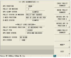 APC Diagnostics Screen 1 |
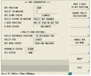 APC Diagnostics Screen 2 |
APC Status Conditions
The APC Diagnostics screen displays the status of inputs for the APC system.
See the Field Glossary for definitions of the fields on the ATC and Diagnostic screens:
|
|
||
|
|
||
|
|
||
|
|
||
|
|
||
|
|
|
APC Diagnostics Softkeys
The APC Diagnostic softkeys are functional only when Servo Power is On and the machine is calibrated. These are the APC Diagnostic softkeys.
-
Cycle Pallet Changer—sets the command to complete a full rotation of the APC Table. This function performs a full APC cycle. The Z axis moves to the APC position, the B axis squares, the APC table raises, the APC table rotates 180 degrees and then lowers.
-
Raise Pallet Changer—sets the command to lift the APC Table to the Up position. The B axis must be squared and the Z axis must be at the APC position.
-
Rotate APC to Position 1—sets the command to rotate the APC table to Position 1 inside the machining area. The B axis must be squared and the APC must be in the raised position, and Position 1 must not be in the machining area.
-
Rotate APC to Position 2—sets the command to rotate the APC table to Position 2 inside the machining area. The B axis must be squared and the APC must be in the raised position, and Position 2 must not be in the machining area.
-
Lower Pallet Changer—sets the command to lower the APC table to the Down position. The Z axis must be in the APC position. The table must be at Pos 1 or Pos 2.
-
More—opens the second APC Diagnostics screen.
-
Move Z-Axis to APC Position—sets the command to move the Z axis to the APC position. The APC table must be in the down position to move the Z axis to the APC position.
-
Square Pallet for Rotation—sets the command to square the pallet.
-
Enable APC Jog Mode—allows the operator to jog the APC table up and down and also jog the APC table 180 degrees. When selected, a message displays indicating to proceed with caution:
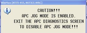
This message is displayed until the APC Diagnostics screens are exited or until an E-stop occurs.
APC Jog Mode
The operator should verify the position of the Z axis before jogging the APC. From APC screen 1, the operator can select Raise Pallet Changer, Lower Pallet Changer, Rotate APC to Position 1, or Rotate APC to Position 2. Once a function has been selected, the green Start Cycle button flashes and a message is displayed:

The operator can then press and hold the green Start Cycle button to jog the APC. The operator must hold the Start Cycle button down while jogging. Once the Start Cycle button is released, the jogging function stops. The operator must select a softkey function again to enable the jogging.
|
|
Once selected, the APC Jog Mode remains enabled until the operator navigates away from the APC diagnostic screens or an E-stop occurs |

When all requirements for a softkey action are met, a prompt displays and the Start Cycle lamp flashes. Pressing the Start Cycle button executes the command. The Start Cycle lamp stops flashing during execution of the command and is turned off when the command is completed.
Selecting another softkey before pressing the Start Cycle button cancels the pending command. If requirements for a softkey action are not met, a message displays indicating why the action cannot be commanded.
Operating the APC from the Load Station
The APC Panel, shown in the figure below, is located on the front of the machine enclosure, below the front enclosure doors. The APC Panel is used to operate the APC table.

APC Panel Pushbuttons
These are the APC Panel pushbuttons:
-
Emergency Stop—disables all axis servo drives and stops all moves of the pallet changer.
-
Cycle Start—initiates the APC to cycle in Auto mode. The Cycle Start pushbutton flashes while the operation is pending, is steady when the operation is in process, and turns off when the operation is completed.
-
Cancel Cycle—cancels any pending operation (if the Cycle Start lamp is flashing, it will turn off). Pressing the Cycle Start pushbutton after an operation is cancelled by the Cycle Stop pushbutton results in no APC motion. This pushbutton does not stop the APC once it has started its cycle.
-
APC Ready—readies the APC for a pallet change. The APC doors must be closed and locked. When pressed, the Cycle Start pushbutton flashes to begin the operation. This pushbutton is used when confirmation is required.
|
|
The console’s Start Cycle pushbutton flashes when the Hydraulic Lift, APC Table Rotate to Position 1, or APC Table Rotate to Position 2 pushbutton is illuminated and the Cycle Start pushbutton is flashing. Pressing the console’s Stop Cycle pushbutton cancels the operation. |

-
Manual Cycle APC—sets the command to complete a full rotation of the APC Table (this pushbutton corresponds to the Cycle Pallet Changer softkey on the APC Diagnostics screen.) This pushbutton is used only in manual or diagnostic mode.
Manual APC Table Rotation
Near the front of the APC table is a Manual Table Release Lever. This lever provides the input for the APC Pin Lock. To manually rotate the table without using the remote APC Panel, pull the Release Lever out. This allows the APC table to be rotated by hand for part setup. After rotating the APC table, the arrows on the pallet must be aligned with the arrows on the APC table’s platform before executing a pallet exchange.
|
|
The APC table must be in Down position before using the Manual Table Release Lever to manually rotate the table. |

|
|
Failure to align arrows prior to executing a pallet exchange can result in the APC table not positioning correctly in the machining area. |
