Program Functions
The Program Functions (M00, M01, and M02) stop the execution of the part programs.
Program Stop (M00)
The Program Stop (M00) cancels the spindle and coolant functions and terminates further program execution after completion of other commands in the same program block. When the program is stopped, existing modal information remains unchanged as in single block operation. The Start Cycle button on the control flashes and this prompt message appears:
Cycle complete; press start to continue.
Pressing the Start Cycle button resumes the spindle and coolant operation and continues the program execution.
This M code should not be set simultaneously with other M codes. M00 is executed following execution of the rest of the address words on the block. Here is an example using the M00 code:
N10 G01 X2. Y1. F10. M00
In this example, the machine moves to the X2/Y1 location before it shuts down.
|
|
Program blocks should be included that retract the tool to a safe position before a block containing an M00 is programmed. If these program blocks are not included, the spindle stops while cutting the part. |

Planned Stop (M01)
The Planned Stop Code (M01) pauses the program and shuts off the spindle. M01 is ignored unless previously validated in the parameter page.
Include a data block to retract the tool to a safe position before a block containing an M01 is programmed. If the retract tool data block is not included, the spindle will stop while cutting the part.
|
|
The enclosure doors can be opened after an M01 command, but no machine operation is allowed. Once the doors are closed, press the flashing Start Cycle button to acknowledge the command and allow the program to continue. |

|
|
You can also pause the program and shut off the spindle by selecting the NC Optional Stop On/Off softkey on the Auto Run screen or setting the NC Optional Program Stop parameter on the NC Configuration Parameters screen. Refer to Auto Mode Monitoring in Getting Started with WinMax Mill and NC Parameters for more information. |

|
|
When the Start Cycle button is pressed after an M01, the control looks ahead 30 blocks to determine if the spindle and/or coolant should be turned back on. For the spindle, a M06, M19, M5, M2, M30 or M36 event without a G01, G02, or G03 will keep the spindle off. For coolant, a M06, M09, M2, or M36 event without a G01, G02, or G03 will keep the coolant off. Otherwise, the spindle and/or coolant is turned back on. |

End of Program (M02)
The End Of Program code (M02) indicates the end of the main program (the completion of the part), and is necessary for the registration of CNC commands from tape to memory. M02 stops the spindle, the coolant, and the axis feed after completing all of the commands in the program. M02 is active after the block is executed. If Program End Shutdown is enabled under Aux/Menu options, M02 begins a countdown to shut down the machine.
|
|
The M02 does NOT stop the NC program loader if the program is loading from a serial link. An E character must be transmitted to signal the loader that the entire program has been sent to the remote device. |
|
|
This M code should not be set simultaneously with other M codes unless it is the last M code in the block. |

Start Spindle Clockwise (M03)
The Start Spindle Clockwise code starts a clockwise spindle rotation (as viewed from the headstock). The spindle reaches the programmed speed before X, Y, and Z (also A and B if present) axis feed starts. If the M03 is on the same line as a Rapid move (G00), the spindle ramps up to speed while moving at rapid to position. If the spindle speed has not been defined, the Tool Setup screen’s spindle speed is used.
M03 is active before the other commands in the block are executed.
Start Spindle Counterclockwise (M04)
The Start Spindle Counterclockwise code starts spindle rotation in a counterclockwise direction (as viewed from the headstock). The spindle reaches the programmed speed before X, Y, Z (A or B) feed starts. If the spindle speed has not been defined, the Tool Setup screen’s spindle speed is used.
M04 is active before the other commands in the block are executed.
Spindle Off (M05)
The Spindle Off code is the default and causes the spindle to stop in a normal manner. If the machine is equipped with a brake, it is applied.
M05 is active after the other commands in the block are executed.
M6 Initiates Tool Change
Use this field on the NC Parameters screen to indicate whether tool changes are initiated with the M6 or with the T code. Set this field to No and the M06 is ignored and tool changes are initiated whenever a T code is found in the program (not when T is used for user-defined subprogram or subprogram parameter).
If this field is set to Yes, the M6 is required for tool changes. (Default is Yes.)
If this field is set to Yes and a T code is used without the M06, the machine will “pre-fetch” the tool. When this occurs, the tool changer moves the tool carousel so the next tool is ready, but does not complete the change until it encounters the M06.
Change Tool (M06)
The Change Tool code requests that the machine perform a tool change. These tool changes should be performed in rapid traverse mode. The following sequence occurs if an automatic tool changer is present and in the Auto Tool Change mode:
-
The Z axis retracts to tool change position.
-
The machine moves the X and Y axes to the Tool Change position if the tool change position parameter is set to Yes.
-
The spindle orients and stops.
-
The “old” tool is returned to the tool changer.
-
The “new” tool is placed in the spindle.
-
New tool offsets from the Tool Offset screen are loaded into the appropriate registers. The Tool Length Offsets from G43 and G44 remain in effect.
-
The program continues.
|
|
The M06 is optional if the M6 Initiates Tool Change field on the NC Parameters screen is set to Yes; otherwise, tool changes are performed with the T code. |

This sequence occurs for manual tool changes:
-
Z axis retracts to its tool change position.
-
The machine moves the X and Y axes to the Tool Change position if the tool change position parameter is set to Yes.
-
The spindle stops and orients.
-
The screen prompts for a tool change.
-
Change the tool and press the Start Cycle button on the control to allow the program to continue.
-
New tool offsets are loaded into the appropriate registers.
-
The program continues.
|
|
The first Z dimension after a tool change must be absolute. Any Z dimension programmed in a tool change block is ignored. |

Secondary Coolant On (M07)
The Secondary Coolant On code switches on the mist coolant, if available. M07 is active before the other commands in the block are executed.
Primary Coolant On (M08)
The Primary Coolant On code switches on the flood coolant, if available. M08 is active before the other commands in the block are executed.
Both Coolant Systems Off (M09)
The Coolant Off code is the default and switches off the coolant if it has been activated by Secondary Coolant On (M07) or Primary Coolant On (M08). M09 is active after the other commands in the block are executed.
Both Coolant Systems On (M10)
The Both Coolant Systems On code switches on the coolant if it has been activated by Both Coolant Systems Off (M09).
Air Through Spindle (M11)
The Air Through Spindle code causes the air to run through the spindle. Air Through Spindle (M11) uses a Q parameter to turn Air Through Spindle On/Off.
Air Through Spindle does not turn off unless commanded to turn off.
Q__ indicates whether Air Through Spindle in turned On or Off.
-
Q1 turns Air Through Spindle On.
-
Q0 turns Air Through Spindle Off.
|
|
Air Through Spindle (M11) and Coolant Through Spindle cannot be in operation at the same time. Ensure both operations do not conflict. |

Clamp C-axis (M12)
The Clamp C axis code clamps the C axis. For C axis moves after M12, the C axis is automatically unclamped for the move and clamped again after the move is complete.
M12 is active before the other commands in the block are executed and is canceled by an Unclamp C axis (M13) command.
Unclamp C-axis (M13)
The Unclamp C axis code unclamps the C axis until an M12 is programmed.
M13 is active before the other commands in the block are executed and is canceled by a Clamp C axis (M12) command.
Automatic Buffering On (M16)
Turns on automatic buffering when the Intelligent Automatic Safe Repositioning parameter is enabled in NC Parameters. M16/M17 are used to turn automatic buffering on and off within a program.
Automatic Buffering Off (M17)
Turns off automatic buffering.
Oriented Spindle Stop (M19)
The Oriented Spindle Stop code causes the spindle to stop in the oriented position. A brake, if available, will be applied. The coolant is also turned off. This function only applies to machines which have an orient feature. On machines without the orient feature, this function works like the Spindle Off (M05) command.
S___ defines the position of the spindle, from 0 to 359 degrees, in 1 degree increments.
Q___ defines the reference method for the spindle zero position:
-
Q0 defines the orient position as the zero position. The spindle position is a positive angle measured CCW from the orient position. This is the default reference method.
-
Q1 defines the positive X axis as the zero position. The spindle position is a positive angle measured counterclockwise from the positive X axis, when looking down the spindle. A position of zero will align the oriented spindle key along the positive X axis.
Example:
M19SxxxQ1 will orient along the X axis at the degree position defined by S
M19SxxxQ0 will orient along spindle orient position at the degree defined by S
M19 is active after the other commands in the block are executed. When the M19 S_ command is received, WinMax will stop the spindle, orient the spindle, move to the S_ position, and then hold position.
Pulse Indexer One Increment (M20)
The Pulse Indexer One Increment code advances the indexer one position. A reply signal is sent back from the indexer to indicate when it is in position. When the signal is received, the program continues. For multiple indexes, separate M20 blocks must be programmed. (Refer to the indexer’s manual and the Hurco Maintenance Manual for information on attaching an indexer to the machine.)
M20 is active after the other commands in the block are executed.
Z Axis to Home Position (M25) - Basic NC Programming only
The Z Axis to Home Position code retracts the Z axis to the home position (tool change height) at the rapid traverse rate selected in the Program Parameters screen. The first Z value after an M25 must be absolute.
M25 is active before the other commands in the block are executed.
Select Part Probe Signal (M26)
When G31 is used to invoke probe motion, the machine will move to the specified destination until either the destination is reached or a probe deflection occurs. The Select Part Probe Signal (M26) alerts the G31 move to detect a part probe deflection.
Select Tool Probe Signal (M27)
When G31 is used to invoke probe motion, the machine will move to the specified destination until either the destination is reached or a probe deflection occurs. The Select Tool Probe Signal (M27) alerts the G31 move to detect a tool probe deflection.
Tap Retract Recovery (ISNC M28)
M28 initiates tap retract recovery in the event of machine abortion during a tapping operation.
Enable Rigid Tapping (ISNC M29)
When Enable Rigid Tapping (M29) is used before a Left-Handed Tapping Cycle (ISNC G74) or Tapping Cycle (G84) command, rigid tapping is performed. M29 stays in effect until a One-Shot (G00, G01, G02, G03) code or Canned Cycle Cancel (G80) command is used.
Program End (M30)
The Program End code (M30) indicates the end of the main program (the completion of the part). M30 stops the spindle, the coolant and the axis feed after completing all of the commands in the program. M30 is active after the block is executed. If Program End Shutdown is enabled under the Aux/Menu options, M30 begins a countdown to shut down the machine.
Rotary Encoder Reset (M31)
M31 resets the rotary part to a position within -180° and +180° reading of absolute position, depending on the actual machine position.
For example, if the rotary axis is positioned to 9000° and the program is rerun, without an M31 the rotary axis unwinds back to the starting point before moving to 9000°. With an M31 before the 9000° move, the rotary axis resets from 9000° to a position within -180° and +180 and does not have to rewind.
An M31 command can be called in both Conversational and NC part programs. If M31 is executed during contouring operations in a part program, the move prior to the M31 command will come to an exact stop before M31 is executed.
Clamp A-axis (M32)
The Clamp A-axis code clamps the A axis. For A axis moves after M32, the A axis is automatically unclamped for the move and clamped again after the move is complete.
M32 is active before the other commands in the block are executed and is canceled by an Unclamp A axis (M33) command.
Unclamp A-axis (M33)
The Unclamp A axis code unclamps the A axis until an M32 is programmed.
M33 is active before the other commands in the block are executed and is canceled by a Clamp A axis (M32) command.
Clamp B-axis (M34)
The Clamp B axis code clamps the B axis. For B axis moves after M34, the B axis is automatically unclamped for the move and clamped again after the move is complete.
M34 is active before the other commands in the block are executed and is canceled by an Unclamp B axis (M35) command.
Unclamp B-axis (M35)
The Unclamp B axis code unclamps the B axis until an M34 is programmed.
M35 is active before the other commands in the block are executed and is canceled by a Clamp B axis (M34) command.
Servo Off Code (M36)
The servos may be turned off using the Servo Off (M36) command.
Control power to the machine will be turned off. The control will still be powered on. This is similar to an emergency stop.
Laser Input Update (M38-M40)
These codes read the state of the three laser inputs (M38: OK signal;
M39: static signal; and M40: dynamic signal).
Single-Touch Probing (M41)
For a G31 probing move, perform one touch.
Double-Touch Probing (M42)
For a G31 probing move, perform two touches. This is the default mode.
Barrier Air Control (M43 and M44)
Barrier air is used to prevent chips and debris from getting into the laser emitter and receiver. M43 causes the air flow at the probe to increase; M44 reduces the airflow. During operation of the probe, the barrier air should be increased whenever the probe shutter is open. It should remain at the high flow rate except during the actual tool measurement. When the shutter is closed, the flow rate may be reduced.
Shutter Probe Control (M45 and M46)
A pneumatic shutter protects the probe. During a measurement, the barrier air should be increased and the shutter opened. After the probe cycle is completed, the shutter should be closed and the barrier air reduced. M45 causes a brief puff of air that helps clear chips and debris from the probe. M46 closes the shutter.
Laser Emitter On/Off Control (M47 and M48)
M47 turns the laser emitter on. M48 turns the laser off. It is recommended to turn the laser emitter off when not in use.
Laser Receiver On/Off (M49 and M50)
M49 turns the laser receiver on. M50 turns the laser receiver off. It is recommended to turn the laser receiver off when not in use.
|
|
M49 is also used to disable latch mode and M50 to enable latch mode with some probe types. |

Cycle Pallet Changer (M51)
M51 rotates the pallet changer on horizontal machining centers without regard to position or pallet setup. Confirmation is required.
Enable Auxiliary Output 1 through 4 (M52 – M55)
M52 through M55 are used to individually enable auxiliary equipment or a unique machine function from within a part program. Enter performance time for the machine-specific M code in the M Code Table. When M52 through M55 are active, the corresponding auxiliary equipment or machine function is turned on, and any performance time is added to estimated run time.
M52 enables Auxiliary Output 1, M53 enables Auxiliary Output 2, M54 enables Auxiliary Output 3, M55 enables Auxiliary Output 4.
|
|
Auxiliary Outputs 5 through 12 are enabled with M142-M149. |

Nonconfirmation Pallet Change (M56 – M58)
M56 rotates the pallet changer without regard to position or pallet setup confirmation. M57 rotates the pallet changer to pallet 1. M58 rotates the pallet changer to pallet 2.
The Z-axis automatically moves to zero when a M56, M57 or M58 command is executed.
Chip Conveyor Fwd/Reverse/Stop (M59, M60, M61)
M59 enables chip conveyor forward mode. M60 enables chip conveyor reverse mode. M61 stops the chip conveyor motion.
Disable Auxiliary Output 1 through 4 (M62 – M65)
M62 through M65 turn off auxiliary equipment or machine functions enabled with M codes M52 through M55.
M62 disables Auxiliary Output 1 (M52), M63 disables Auxiliary Output 2 (M53), M64 disables Auxiliary Output 3 (M54), and M64 disables Auxiliary Output 4 (M55).
Washdown Coolant System (M68, M69)
M68 enables washdown coolant system. M69 disables washdown coolant system.
Pallet Changer Control (M70)
M70 controls pallet changes with or without two optional parameters, P_ and L_. By itself (without P_ or L_ parameters) it cycles the pallet changer without confirmation. Confirmation requires the APC Ready button.
M70 P_ L_ (optional)
where
P0 = change current pallet (no P token is the same as P0)
P1 = change to pallet #1
P2 = change to pallet #2
L0 = perform pallet change without confirmation (no L token is the same as L0)
L1 = perform pallet change with confirmation (APC Ready button)
Z Axis Retract Enable (M90)/Disable (M91)
M90 enables the Z Axis to be retracted in the event of a power loss. M91 disables Z retract.
M90/M91 must be used with the Enable Retract Z-Axis on Power Loss parameter. The parameter must be set to 1 to enable the feature, and can then be turned on and off within a program using M90 (on) and M91 (off).
Enable Spindle Interrupt (M93)
M93 enables spindle interrupt, which halts the spindle during execution of a program.
Disable Spindle Interrupt (M92)
M92 disables spindle interrupt (M93).
Subprogram Call (M98)
One way of specifying the number of iterations for a subprogram to perform is with M98 subprogram calls.
When making M98 subprogram calls, the P parameter is used to specify iterations as well as the subprogram number. Up to four digits can be used to specify iterations for a maximum of 9999 iterations. Leading zeros are not required when specifying iterations; however, leading zeros are required with a subprogram number that is less than 1000.
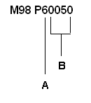
In Example 1 below, M98 P60050 must be used instead of M98 P650 to run program 50 with 6 iterations because the subprogram number (50) is less than 1000.
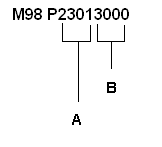
In Example 2, the M98 P23013000 subprogram example, the four digits to the left (2301) specify the number of iterations, and the four digits to the right (3000) specify the subprogram number.
|
Example 1 |
Example 2 |
|
|
|
|
A |
Number of Items |
|
B |
Subprogram Number |
As other examples, M98 P1 runs program 1 with no iterations, and M98 P100001 runs program 1 ten times.
Jump; Return from Subprogram (M99)
Each subprogram ends with an M99 Jump statement.
Shortest Rotary Angle Path Traverse (M126) and
Shortest Rotary Angle Path Traverse Cancel (M127)
M126 activates Shortest Rotary Angle Path Traverse. The control will move the rotary-axis through the shortest angular distance to the commanded position. M127 cancels the Shortest Rotary Angle Path Traverse.
Example
The table below illustrates machine movement with the M126 command.
|
Initial Position |
Commanded Position |
Angular Distance Traverse |
|---|---|---|
|
350° |
20° |
+30° |
|
20° |
350° |
-30° |
Machine Movement with M126 Command
The table below illustrates machine movement with the Shortest Rotary Angle Path Traverse Cancel (M127) command. Standard machine movement for the VMX42 SR is the same as machine movement with the Shortest Rotary Angle Path Traverse cancelled, except when Tool Vector Input (G00 or G01) or 3D Tool Geometry Compensation (G41.2) are active.
|
Initial Position |
Commanded Position |
Angular Distance Traverse |
|---|---|---|
|
350° |
20° |
-330° |
|
20° |
350° |
+330° |
Machine Movement with M127 Command
Tool Center Point Management (M128) and
Tool Center Point Management Cancel (M129)
The Tool Center Point Management feature allows programming of 5-axis tool positions in the Workpiece Coordinate System, independent of the Part Setup location in the machine. Refer to the Getting Started with WinMax Mill manual.
M128 activates Tool Center Point Management and M129 cancels Tool Center Point Management.
|
|
G00, G01, G02, and G03 moves are supported in M128 mode. NC Hole cycles are permitted with M128 activated, only if the Tool Vector is vertical. Both G93 (Inverse Time) and G94 (UPM) are supported when M128 is active. |

Three input modes are available with M128:
-
Axes Angle Input (G00 or G01): Tool Bottom Centerpoint (X_Y_Z_) and Axes Angle Input (B_C_)
-
Tool Vector Input (G00 or G01): Tool Bottom Centerpoint (X_Y_Z_) and Tool Vector (I_J_K_)
-
3D Tool Geometry Compensation (G41.2): Surface Contact Point (X_Y_Z_) and Tool Vector (I_J_K_) and Surface Normal Vector at contact point (U_V_W_)
Axes Angle Input
Allows the Operator to specify the Tool Bottom Centerpoint with respect to the Workpiece Coordinate System, and the rotary and tilt axes relative to the Unrotated Coordinate System. Refer to the Getting Started with WinMax Mill manual.
Format
G01 X_Y_Z_B_C_
where
{X, Y, Z} is the Tool Bottom Centerpoint.
{B, C} are the rotary and tilt angles relative to Part Setup. B and C are modal.
Tool Vector Input
|
|
Tool Vector Input is only available if M128 or NC Transform Plane is active. |

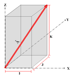
A vector is a direction in 3D space that is defined using values for the X, Y, and Z direction components, as shown in the figure below. Since vectors describe a direction, their base is always at the Coordinate System origin from which they point outward. Tool Vector is the vector that describes the orientation of the tool axis; the direction from the tool tip pointing up through the spindle and away from the workpiece.
|
|
The Tool Vector can be specified with up to six decimal places. It is highly recommended that the full precision be used. Field values will normally lie in the range of -1.000 000 to +1.000 000. If the magnitude of the vector does not equal 1, the vector will be normalized by the CNC. The magnitude of a vector is determined by using the following equation: |

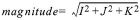
The drawing below is a plot of a vector with its, Â I, J, and K components that correspond to the X, Y, and Z directions.
When the NC program contains Tool Vectors in the tool position blocks with M128 or NC Transform Plane active, the CNC will compute the appropriate rotary and tilt axes (B-axis and C-axis) positions. The Tool Tip location in the part program specifies where on the workpiece the tool should be positioned. The CNC computes the X, Y, and Z machine axes positions to move the rotated tool tip to the specified point on the rotated workpiece.
|
|
The Tool Tip and Tool Vector are specified with respect to the Workpiece Coordinate System defined in the CAM software or the NC Transform Plane. The CNC will automatically compute the machine axes positions using the Tool Length and the Part Setup information. Refer to Getting Started with WinMax Mill. |

Format
G01 X_Y_Z_I_J_K_
where
{X, Y, Z} is the Tool Bottom Centerpoint. X, Y, and Z are modal.
{I, J, K} is the Tool Vector. I, J, and K are non-modal.
|
|
Both G93 (Inverse Time) and G94 (UPM) are supported with Tool Vector Input. |

3D Tool Geometry Compensation (G41.2)
|
|
M128 must be active when using G41.2. |

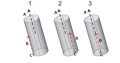
G41.2 allows specification of the Surface Contact Point, the Surface Normal Vector, and the Tool Vector. The CNC will compute the tool position automatically for ball nose, flat end, and bull nose endmills. The tool will be positioned to tangentially touch the specified Surface Contact Point. The following figure shows the Surface Normal Vector, Tool Vector and Surface Contact Point for a tool.
|
1 |
Surface Normal Vector |
|
2 |
Tool Vector |
|
3 |
Surface Contact Point |
|
|
Although ball, flat, and bull nose endmills can be positioned interchangeably with a G41.2 command, there is no guarantee that the selected tool dimensions and geometry will not cause gouging of the part. It is the responsibility of the Operator to ensure that the tool path is gouge-free for the selected tool. |

The Surface Contact Point, Surface Normal Vector, and Tool Vector are specified with respect to the Workpiece Coordinate System defined in the CAD/CAM software or part drawing. The CNC will automatically compute the machine axes coordinates using the tool dimensions and Part Setup information. Refer to Getting Started with WinMax Mill.
|
|
Tool Vector and Surface Normal Vector can be specified with up to six decimal places. It is highly recommended that the full precision be used. Field values will normally lie in the range of -1.000 000 to +1.000 000. If the magnitude of the vector does not equal 1, the vector will be normalized by the CNC. |

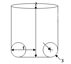
For flat and corner radius end mills, there are infinite solutions for the tool position when Tool Vector and Surface Normal Vector point in the same direction and any point on the bottom face of the tool can touch the Surface Contact point (shown by #1 and #2 in the following figure). When this condition exists, the CNC will place the Tool Bottom Center on the Surface Contact Point, as shown by #3 in the figure below.
|
A |
Tool Vector |
|
B |
Surface Normal Vector |
|
C |
Surface Contact Point |
-
G41.2 requires the radius and corner radius to compute tool positions. Refer to the following figure for tool geometry.
-
G41.2 D_R_ specifies the Tool Radius (D_) and the Corner Radius (R_) for both the ISNC and Hurco Basic NC dialects. The values in D_ and R_ are indexes for the Tool Radius Offset Table and Tool Corner Radius Offset Table, respectively.
|
1 |
Radius |
|
2 |
Tool Length (spindle zero to tool tip) |
|
3 |
Corner Radius |
Format
|
|
G41.2 uses G01 for contouring moves. G40 cancels G41.2 |

G01 X_Y_Z_I_J_K_U_V_W_
where
All coordinates are specified in the Workpiece Coordinate System. Refer to Getting Started with WinMax Mill.
{X, Y, Z} is the part’s Surface Contact Point and is modal.
{U, V, W} is the Surface Normal Vector of the part contact point and is modal. Its default coordinates are 0, 0, 1.
{I, J, K} is the Tool Axis Vector and is modal. Its default coordinates are 0, 0, 1.
|
|
3D Tool Geometry Compensation (G41.2) is well-suited for using with a ball nose endmill. The potential for surface gouging exists when using the G41.2 command with flat and corner radius endmills. |

Tool Clamp (M135)
M136 Tool Clamp clamps the tool in the spindle during a program run, typically after a manual tool change.
Tool Unclamp (M136)
M136 Tool Unclamps the tool in the spindle during a program run, typically to perform a manual tool change.
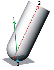
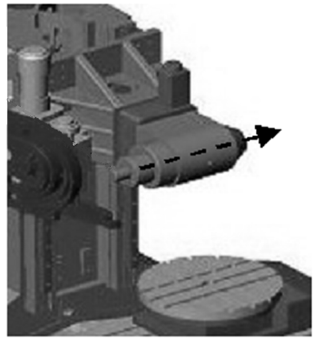
Retract Along Tool Vector (M140)
M140 allows the Operator to move the tool along the current Tool Vector for a specified distance or to retract to machine limits. In the drawing below, positive Retract Along Tool Vector is in the direction of the arrow (which will move the tool away from the part).
Format
M140 is non-modal and is only active for the current block.
M140 [L_], where L_ is the incremental distance the tool will move from its current position along the current Tool Vector direction.
-
A positive L_ value will move the tool in the direction pointing from the cutting tool bottom up through the spindle (i.e., moves the tool away from the part). Typically, a positive L_ value will be programmed.
-
A negative L_ value will move the tool in the opposite direction.
-
When M140 is used without the L_ parameter, the tool will retract along the positive direction of the current Tool Vector to the machine limits (i.e., move the tool tip away from the workpiece).
Tool Vector Input Off(M141)
M141 is used after specifying an IJK tool vector to turn off the modal tool vector input state.
|
|
M141 is deprecated in WinMax v10.2 |

Enable Auxiliary Output 5 through 12 (M142-M149)
M142 through M149 are used to individually enable auxiliary equipment or a unique machine function from within a part program. Enter performance time for the machine-specific M code in the M Code Table. When M142 through M149 are active, the corresponding auxiliary equipment or machine function is turned on, and any performance time is added to estimated run time.
M142 enables Auxiliary Output 5, M143 enables Auxiliary Output 6, M144 enables Auxiliary Output 7, M145 enables Auxiliary Output 8, M146 enables Auxiliary Output 9, M147 enables Auxiliary Output 10, M148 enables Auxiliary Output 11, and M149 enables Auxiliary Output 12.
|
|
Auxiliary Outputs 1 through 4 are enabled with M52-M55. |

Disable Auxiliary Output 5 through 12 (M152 – M159)
M152 through M159 turn off auxiliary equipment or machine functions enabled with M codes M142 through M149.
M152 disables Auxiliary Output 5 (M142), M153 disables Auxiliary Output 6 (M143), M154 disables Auxiliary Output 7 (M144), M155 disables Auxiliary Output 8 (M145), M156 disables Auxiliary Output 9 (M146), M157 disables Auxiliary Output 10 (M147), M158 disables Auxiliary Output 11 (M148), and M159 disables Auxiliary Output 12 (M149).
B-Axis Pinning (M170 - M175)
The B-Axis on boring mill machines can be locked, or “pinned.” M170 through M175 are used to specify the pinning position (machine position):
-
M170—Table select B to 0 degrees and pin
-
M171—Table select B o 90 degrees and pin
-
M172—Table select B to 180 degrees and pin
-
M173—Table select B to 270 degrees and pin
-
M174—Table pin in (must be at one of the above positions)
-
M175—Table pin out (must be at one of the above positions)
Spindle Gear Select (M176)
M176 selects the spindle gear. Applicable only on machines that have multi-speed spindles.
Format is M176 Pn, where n is gear number 1-5. Once a spindle gear is specified, it remains active until the gear is changed with another M176.
ASR Non-Interpolated Axis Motion (M177)
M177 is used to select interpolation of co-linear axes. Axis selection remains in effect until a change is made in another M177 call or when Tool Center Point Management (M128) or the transform plane ends.
|
|
M177 requires a transform plane or Tool Center Point Management (M128) to be active in the program. |

Format
M177 U[0,1] V[0,1] W[0,1] L[0,1]
where
U, V, W are the X, Y, Z co-linear axes, respectively.
0 disables interpolation for the axis.
1 enables interpolation for the axis.
L0 (default) enables ASR non-interpolated axis motion.
L1 disables ASR non-interpolated axis motion.
|
|
Ensure the disabling of ASR non-interpolated axis motion will not result in a tool collision. |

Using M177 on a Boring Mill
Position interpolated axes to the desired location before switching interpolation to a different axis. To position the axes in a conversational program, place a position block just before the transform plane and M177. After switching interpolated axes, the non-interpolated axis remains in its last position until it’s programed to move. Refer to Position Data Block for more information on using the Position Data block in a program.
Tool Changes
Tool changes (manual or ATC) cause the non-interpolated axis to move to the tool change position. After a tool change occurs in a conversational program, the non-interpolated axis is returned to its pre-tool change position at the appropriate time. NC programs that are on a transform plane or in Tool Center Point Management (M128) mode return non-interpolated axes positions immediately following a tool change.
ASR Motion
Repositioning a rotary axis requires a retract to a safe position to avoid colliding the tool and the part. Non-interpolated axes retract along with interpolated axes. WinMax automatically moves non-interpolated axes efficiently with the interpolated partner axes when possible, increasing the speed of retract and plunge operations.
Set Max Rapid (M194)
M194 is used to set the maximum rapid rate for the program. M194 requires an argument to specify the maximum rapid rate.
M94 Example:
M94:5080
This block sets the Maximum Rapid Rate to 5080 MMPM (200 IPM).
Tilt Axis Preference (M200)
To improve the work volume when the spindle is horizontal, the C axis table has been located at the corner of the machine's base table. Although this configuration provides a large work volume for negative B axis angles, it restricts the work volume for positive B axis angles. Since parts that require positive B axis angles can be cut using a negative B axis angle with a rotation of 180 degrees of the C axis table, the configuration does not impose limitations on the parts that the user can cut.
|
|
Since positive B-axis angles have a restricted work volume for |

M200 can be used to select the Tilt Axis Preference direction for simultaneous 5-axis contouring in an NC program. A positive Tilt Axis Preference will keep the B axis between 0 to +90 degrees. A negative Tilt Axis Preference will keep the B axis between -90 to 0 degrees. A neutral Tilt Axis Preference specifies no preference and the program will execute with the shortest angular traverse if activated. A Neutral, Positive, and Negative preference is specified using P0, P1, or P2 parameter with the M200 command.
Tilt Axis Preference is only applied under the following conditions:
-
Tool Center Point Management (M128) OR Transform Plane is active.
-
AND Tool Vector input is used.
OR
-
Cylindrical wrap machining (G07.2) is used.
|
|
Note that during 5-axis simultaneous interpolated moves, if the machine is not on the tilt axis preference side, it can only move back to the preference side when the tool path moves through the machine singularity point (i.e. B0 machine position). |

The default for programs is specified in the Rotary Parameters settings screen.
Motion During 5-axis Contouring with Tilt Axis Preference
If the B axis is requested to move to the opposite side of the Tilt Axis Preference, the CNC will interpolate the tool tip and tool vector up to the machine singularity point (B axis at 0 degrees), then the machine will rotate about the singularity point (i.e. the CNC will rotate the C axis and interpolate the X- and Y axes while keeping the tool tip at a constant location relative to the workpiece), followed by interpolating the B axis and tool tip to their final positions with the B axis on the Tilt Axis Preference Side.
Format
M200 P[0,1,2]
P0 = None (turns tilt axis preference off), control uses shortest angular traverse
P1 = Positive, B axis between [0°, +90°]
P2 = Negative, B axis between [-90°, 0°]
Axis Limit Overrides (M210, M211, M212)
Axis limit overrides allow new minimum and maximum travel limits to be set for an axis.
|
|
Before changing an axis limit be sure the current machine position is within the new limits or an out of limits error will be generated. Before a tool change is executed the limits should be restored to defaults using the M212 to avoid an out of limits error. |

Minimum Axis Limit Override (M210)
Use M210 to set a new minimum axis limit during machining, overriding the default real machine limits.
M210 X_Y_Z_A_B_C_, where the value following the axis is the new minimum limit.
Maximum Axis Limit Override (M211)
Use M211 to set a new maximum axis limit during machining, overriding the default real machine limits.
M211 X_Y_Z_A_B_C_, where the value following the axis is the new maximum limit.
Cancel Axis Limit Overrides (M212)
M212 cancels the axis limit overrides (M210 / M211) and restores the default real machine limits. Limits are also restored to defaults when the program ends.
Kinematic ASR Motion (M213)
M213 is used to specify various aspects of motion when Kinematic ASR (M214) is enabled. M213 optional; when not present the control uses the defaults for the specified parameters.
M213 [L_ | R_] P_ Q_ Z_, where
|
|
L_ and R_ are mutually exclusive and only the last one specified is active. R_ is valid only in Absolute Tool Length mode. |

Kinematic ASR On/Off (M214)
M214 enables or disables Kinematic ASR. Kinematic ASR applies only to rotary axes with motion limits. If the control detects that axis motion limits will be reached, Kinematic ASR retracts and reorients the tool so cutting can continue without going out of limits.
M214 L_, where L0 disables and L1 enables kinematic ASR (default is enabled)
Increment Part Count (M230)
M230 increments the part count in the program cycle. When M230 is read in a program, it increases the part count by 1. In addition to NC, M230 can be added to a program using the Machine Function conversational data block. Refer to Machine Function for more information about using the Machine Function conversational data block in a program.
To avoid incorrect part counts due to program cycle interruptions, place the M230 code in the program location where the part is considered complete.
Override Lockout Off/On (M248 and M249)
M248 uses the value specified by the Feedrate Override dial (FPM % or FPR %, depending on active feed mode). M249 ignores the value specified by the Feedrate Override (FPR % or FPR %, depending on active feed mode) and uses the programmed feedrate. Execute before tool change or motion.